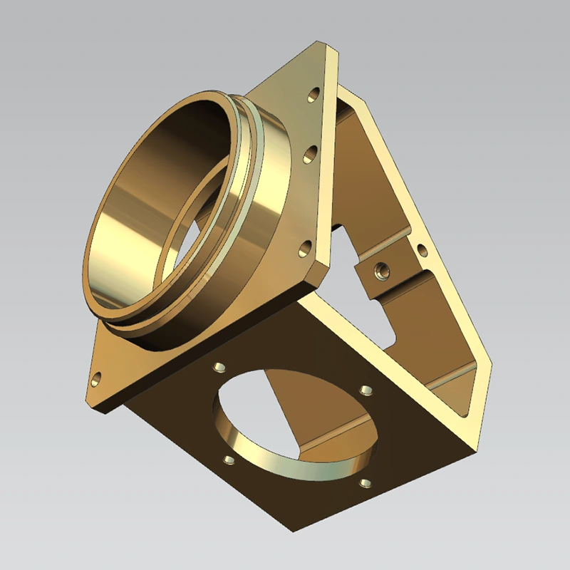
Geometric Tolerance Control in Precision Machining Process is a specialist supplier holding roundness 0.0005-0.005mm, flatness 0.0005-0.015mm and runout 0.002-0.03mm. Traceable 0.002mm CMM reports support transmission, hydraulic and medical programs from samples to series output.
Size alone never guarantees that a bore will seal, a shaft will run true, or a mold half will close without flash. As a precision factory processing geometric tolerance control in precision machining process, Sanluo Precision treats form, orientation and location callouts as first-class requirements alongside diameter: roundness 0.0005-0.005mm, flatness 0.0005-0.015mm, perpendicularity 0.001-0.02mm, concentricity 0.002-0.015mm, runout 0.002-0.03mm and position tolerance 0.002-0.05mm are processed, measured and reported on the shop floor in Shenzhen, where the company has run precision machining for over 18 years across a nearly 8,000 square meter facility.
Size tolerance limits how far a dimension may stray from its nominal value; geometric tolerance limits the form and orientation of the feature itself. A shaft can sit inside a diameter band of ±0.001mm and still run out because it is bowed or tapered; a bore can meet its H7 size and still tilt relative to its face, jamming the piston once assembled. Under geometric tolerance control in precision machining process, datum reference frames are established first, and every form, orientation and location callout is measured against those datums rather than against a standalone dimension. This changes how the process plan is written: the datum surfaces are machined and verified before the controlled features are cut, so the geometric callout has a reference to lean on.
In rotating assemblies, roundness and concentricity determine bearing seating and vibration; in sealing assemblies, flatness and perpendicularity of the face decide whether a seal compresses uniformly; in stacked tooling, the position tolerance of hole patterns decides whether mating parts assemble without forced alignment. The machine itself is specified to match this requirement: workstation geometric accuracy reaches flatness 0.0003, parallelism 0.001, perpendicularity 0.001, symmetry 0.002 and position tolerance 0.002 per mm, meaning the machine's own departure from ideal geometry is smaller than most of the customer drawing callouts it is asked to produce.
Flat, parallel and square datums are the foundation on which every other geometric callout depends; if the base surface is not flat or the bore axis is not square to it, concentricity and position downstream cannot be recovered. The capability data below summarize the tolerance envelope, workstation accuracy, the machining methods used, the inspection assurance in place and the dedicated equipment behind geometric tolerance control in precision machining process.
Sanluo Precision's tight tolerance machining implements strict tolerance control: Dimensional tolerance (diameter IT0 grade ±0.0002mm-IT1 grade ±0.001mm, length tolerance ±0.002-0.015mm); fit tolerance (shaft h2/h3 grade, hole H2/H3 grade, tolerance zone ±0.002-0.008mm); geometric tolerance (roundness 0.0005-0.005mm, flatness 0.0005-0.015mm, perpendicularity 0.001-0.02mm, concentricity 0.002-0.015mm, runout 0.002-0.03mm, position tolerance 0.002-0.05mm); surface roughness Ra0.05-1.6μm.
|
dimensional accuracy |
L(X) |
W(Y) |
H(Z) |
SW |
GD |
|
unit:±/mm |
0.001 |
0.0005 |
0.0001 |
0.002 |
0.001 |
|
Geometric accuracy |
flatness |
parallelism |
perpendicularity |
symmetry |
Position tolerance |
|
unit:±/mm |
0.0003 |
0.001 |
0.001 |
0.002 |
0.002 |
|
production capacity |
1~999999 pcs |
1~999999 pcs |
1~999999 pcs |
1~999999 pcs |
1~999999 pcs |
|
production cycle |
3-20 days |
3-20 days |
3-20 days |
3-20 days |
3-20 days |
Sanluo Precision's processing plant adopts a variety of machining technologies for tight tolerance machining: precision turning (diameter φ0.05-500mm, tolerance IT6 grade ±0.003-0.006mm, roundness 0.003mm), precision milling (flat tolerance ±0.002mm, hole position tolerance ±0.015mm), precision grinding (cylindrical grinding/internal grinding/surface grinding, tolerance IT5 grade ±0.001mm, roundness 0.001mm), precision boring (aperture φ10-500mm, tolerance IT5 grade ±0.002-0.01mm), precision drilling (diameter φ0.1-50mm, position tolerance ±0.02mm), jig boring (hole position accuracy ±0.002mm, for precision molds/fixtures).
As a professional manufacturer of tight tolerance machining, Sanluo Precision implements strict inspection assurance: dimensional inspection (CMM measuring accuracy 0.002mm for measuring dimensional tolerance/hole distance tolerance; laser instrument/ultra-precision micrometer/micrometer/vernier caliper/plug gauge/ring gauge/thread gauge for detecting diameter/length tolerance); Application cases: precision molds (cavity dimensional tolerance ±0.01mm, stamping die gap tolerance ±0.005mm), precision fixtures (locating pin hole H7 grade ±0.005mm, positioning accuracy ±0.01mm), measuring instruments (micrometer anvil flatness 0.003mm, plug gauge tolerance ±0.002mm), precision transmission (gear tooth profile IT6 grade, bearing inner and outer rings IT5 grade ±0.002mm), hydraulic and pneumatic (cylinder bore H7 grade ±0.006mm, spool fit tolerance ±0.003mm). We have directly or indirectly provided customized high precision machining services to Bosch, ZF, NSK and other enterprises, with an annual output of 200,000 pieces and a qualification rate of 99.8%.
|
Parameter Category |
Parameter Details |
|
Equipment Model |
JDSGT400 Linear Motor Driven 3-axis High-Speed Machining Center |
|
Core Positioning |
For submicron-level ultra-high precision machining |
|
Drive System |
All three axes adopt dual linear motor drive |
|
Key Accuracy |
Repeat positioning accuracy up to 0.8 microns; hole position accuracy less than 1 micron within 100 mm range. |
|
Core Technology |
Integrates direct drive, temperature control, self-developed JD60 CNC system precision machining features and high-precision servo drive system |
|
Core Advantage |
Committed to achieving the excellent effect of "surface is the functional surface" |
|
Typical Application |
tight tolerance machining of precision optical molds, semiconductor parts, high-precision structural parts and other products with strict requirements on dimensions and surface quality |
|
Parameter Category |
Parameter Details |
|
Equipment Model |
Micro5 Micron-level High-precision 5-axis Machining Center |
|
Core Positioning |
High dynamic performance and high-precision machining of miniature, high value-added parts |
|
Key Accuracy |
Repeat positioning accuracy 0.0005mm, positioning accuracy < 0.002mm |
|
Spindle System |
Maximum spindle speed 60,000 rpm |
|
Structural Features |
Compact structure with total weight 550kg; equipped with three-layer tool magazine with capacity of 60 tools; processing area pallet system can hold 6 zero-point fixtures |
|
Energy Saving and Environmental Protection |
Extremely low energy consumption (<500W), equipped with oil mist collector |
|
CNC System |
German Beckhoff system |
|
Stroke (X/Y/Z) |
78 / 56 / 50 mm |
|
Typical Application |
tight tolerance machining of miniature engineering components, small precious metal parts, etc. |
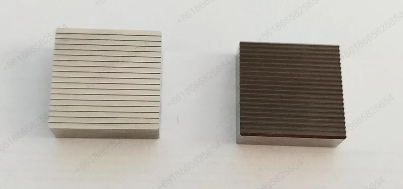
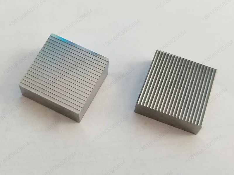
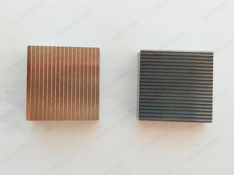
Within these ranges, surface grinding at IT5 ±0.001mm and roundness 0.001mm, together with precision milling at flat tolerance ±0.002mm, are the primary methods used to establish planar datums, while cylindrical grinding and internal grinding carry the coaxial bores and journals.
Rotating and locating features are held inside defined windows so that assemblies seat and locate predictably rather than by chance. The three control windows below are the ones most often specified on turned, bored and jig-bored components:
1. Concentricity: held at 0.002-0.015mm between coaxial diameters, typically achieved through one-setup turning followed by cylindrical grinding, and used for bearing seats, gear hubs and stepped shafts where two diameters must share an axis.
2. Runout: controlled at 0.002-0.03mm total indicator reading across rotating surfaces, managing the wobble of sealing faces, flange mating surfaces and the contact path of rollers against races.
3. Position tolerance: held at 0.002-0.05mm for hole patterns and bolt circles, supported by jig boring at ±0.002mm hole position and verified on the CMM against the datum reference frame.
For bearing rings specifically, IT5 grade ±0.002mm is held on inner and outer races, matching the precision transmission requirement where gear tooth profile is produced to IT6 grade.
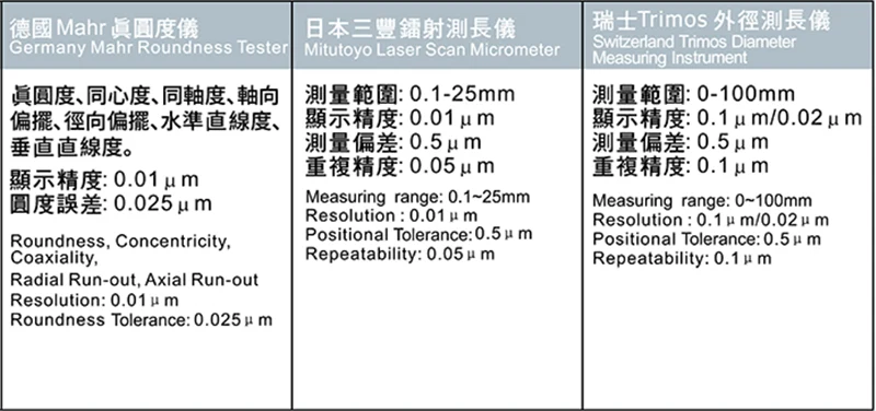
Geometric features are measured with instruments matched to the callout, not only with calipers, because a handheld tool cannot resolve a 0.0005mm flatness or a coaxial runout. The measurement chain below mirrors the way geometric tolerance control in precision machining process is verified on the shop floor:
1. CMM at 0.002mm: the coordinate measuring machine resolves flatness, parallelism, perpendicularity, concentricity and position tolerance against the part's datum reference frame, producing a report that shows the actual deviation vector rather than a pass/fail verdict only.
2. Laser instrument and ultra-precision micrometer: used for length comparison and ultra-fine diameter checks on ground cylindrical features where sub-micron resolution is required, cross-checked against gauge blocks.
3. Plug gauge, ring gauge and thread gauge: verify the functional fit of H2/H3 bores, h2/h3 shafts (tolerance zone ±0.002-0.008mm) and threaded interfaces, confirming assembly compatibility independently of the geometric report.
The inspection fleet exceeds 320 units overall, including automatic three-coordinate measuring machines, image analyzers, tool microscopes, high-power and stereoscopic microscopes, projectors, height gauges, roughness testers and micrometers, so that each geometric callout has a dedicated measurement method rather than a single universal instrument.
When geometric callouts are controlled to the datums, the downstream assembly behaves as the designer intended; deviations typically surface later as noise, leakage or forced fit rather than as a measurable out-of-tolerance dimension. The observable effects on assembly performance fall into four groups:
● Alignment: concentricity and position tolerance keep mating axes collinear, so shafts and bores meet without side load and bearings seat on the full race rather than on a contacting edge.
● Face seating: flatness and parallelism keep flanges, mold halves and fixture plates seated fully, distributing clamping force evenly and preventing the localized gap that causes flash or bolt loosening.
● Rotating accuracy: roundness and runout determine bearing seating quality, vibration and dynamic balance in transmission, pump and spindle components, where a 0.002mm runout change is felt as audible noise over time.
● Seal and fit stability: perpendicularity of bores to their faces controls seal compression, and the h2/H3 fit zone of ±0.002-0.008mm decides clearance or interference behavior as temperature cycles.
In hydraulic applications this translates directly into cylinder bore at H7 ±0.006mm and spool fit at ±0.003mm, held so that the valve moves without binding and without leaking past the spool.
Geometric data only has procurement value if it is documented and traceable. Every shipped batch is accompanied by an inspection report listing the called-out dimensions, the geometric features measured, the instrument used and the measured deviation against the datum frame; first-article reports capture the setup before production is released, so any later drift can be compared back to the original baseline. The quality system follows ISO9001:2008 and ISO14001:2004, with 16 quality personnel split across QE, IQC, IPQC and OQC gates.
At an annual output of 200,000 pieces, the process runs at a 99.8% qualification rate, and non-conforming geometric features are quarantined at the IPQC or OQC gate rather than released. Production capacity spans 1~999999 pcs with a 3-20 day cycle for tolerance-controlled work, supporting both one-piece development orders and series programs that feed directly or indirectly into Bosch, ZF and NSK supply chains. This documentation discipline is what makes the process auditable by customer quality teams, because each number on the report traces back to a measured feature on a named instrument rather than to a process estimate.
Geometric tolerance control in precision machining process is therefore not an add-on to size machining: datums are established first, form, orientation and location windows are processed and measured against those datums, and CMM-backed reports travel with each batch. Drawings that call out concentricity, runout or position tolerances can be quoted with a first-article geometric report attached, so the engineering review rests on measured data from the actual setup.
A: A size tolerance, such as a diameter band of ±0.001mm or a length tolerance of ±0.002-0.015mm, limits how far a dimension may stray from its nominal value. A geometric tolerance limits the shape, orientation or location of a feature, regardless of its size: roundness controls the circularity of a bore, flatness controls how planar a surface is, perpendicularity controls whether a hole axis sits 90 degrees to a face, and position tolerance controls where a hole pattern sits relative to a datum. A part can pass every size callout and still fail geometrically, which is why both are specified and both are reported.
A: Roundness on turned and ground cylindrical surfaces is verified through CMM measurement and roundness-capable instruments, supported by the process capability of cylindrical, internal and surface grinding at IT5 ±0.001mm with roundness 0.001mm. Flatness on faces and datums is measured on the CMM at 0.002mm measuring accuracy and cross-checked against the workstation's own flatness accuracy of 0.0003mm per mm, with surface roughness confirmed on roughness testers as part of the same report. On measuring-instrument work such as micrometer anvils, flatness around 0.003mm is a called-out requirement rather than a by-product.
A: Concentricity controls whether the midpoints of a coaxial circular feature lie on a common datum axis; it is a centerline relationship. Runout controls how much the surface itself wobbles when the part is rotated about that datum axis, measured as total indicator reading. Runout at 0.002-0.03mm absorbs both centerline offset and surface form error, while concentricity at 0.002-0.015mm isolates the axis relationship. In practice, rotating parts that must seal or contact races are typically specified with runout, while stepped bores and gear hubs that must assemble on a common axis are specified with concentricity.
A: Yes. Each shipment is accompanied by an inspection report that lists the called-out dimensions and geometric features, the instrument used (CMM at 0.002mm accuracy, micrometer, plug/ring gauge and so on), and the measured deviation against the datum reference frame. First-article reports are prepared before batch release, so that customer engineering teams can validate the setup before production continues. The 16 quality personnel across QE, IQC, IPQC and OQC own the release of these reports under the ISO9001:2008 and ISO14001:2004 system.
A: Yes. Mechanical design and process engineers on the team review drawings before quoting, and flag callouts that are ambiguous, over-specified for the process, or inconsistent with the datum reference frame. Where a geometric callout is tighter than the practical process window, the process engineer will propose an alternative that still meets the assembly function, such as moving control from a difficult internal bore runout to an external datum that is easier to grind and verify. This review happens during the quotation stage, normally returned within 0-2 days, and design options within 1-3 weeks where redesign discussion is needed.
A: Non-conforming geometric features are quarantined at the IPQC or OQC gate rather than released, because a part that passes size but misses a runout or perpendicularity callout will still cause assembly problems downstream. The quality engineer then traces the deviation back to the setup, the tool or the thermal condition, corrects the process for the balance of the batch, and documents the disposition in the inspection record. Across tolerance-controlled work at 200,000 pieces annual output, the qualification rate stands at 99.8%, and the disposition record is retained alongside the batch report for traceability.