
Abstract
This in-depth technical guide breaks down the complete technical framework of Precision NC Machining, covering constant temperature workshop environment control, multi-process composite cutting, real-time error compensation, and high-end machine tool configuration standards for ultra-precise component manufacturing. The article compares turning, milling, grinding and boring precision indexes, sorts core production equipment parameters, and analyzes standardized manufacturing workflows for optical, medical and metrology-grade parts.
- 1. Core Environmental Control Foundation For Sub-Micron Manufacturing
- 2. Complete Precision Index Parameter Table For Multi-Axis Processing
- 3. Real-Time Error Compensation Core Technical System
- 4. Two Categories Of Ultra-Precision Production Equipment
- 5. Standardized Composite Machining Production Flow
- 6. High-End Industry Application Fields For Precision Components
- 7. Technical FAQ For Precision Manufacturing Engineers
- 8. Long-Term Batch Consistency Value Of Controlled Machining
- 9. Professional Ultra-Precision Manufacturing Cooperation Channel
1. Core Environmental Control Foundation For Sub-Micron Manufacturing
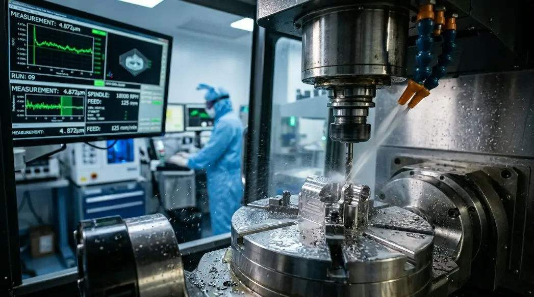
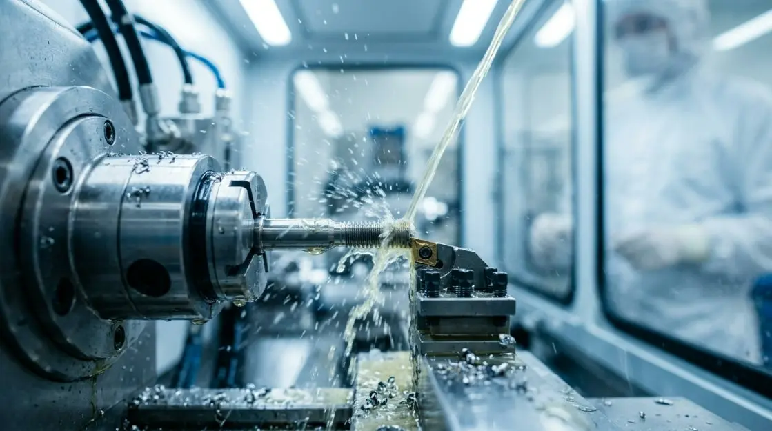
Ultra-tiny dimensional deviations can render high-end optical and medical components unusable, which makes stable manufacturing surroundings the primary prerequisite for consistent micro-scale cutting performance. Precision NC Machining relies on fully sealed constant temperature workshops to eliminate thermal expansion errors that are the top source of dimensional drift in ordinary machine shops.
The standardized constant temperature environment maintains a fixed temperature value of 20±0.5℃ alongside stable 50±5% relative humidity all day long. Minor temperature fluctuations below 1 degree Celsius will trigger measurable expansion of metal blanks, machine spindle assemblies and cutting tools, creating micron-level tolerance over long machining cycles. Vibration isolation foundation treatment under every machine tool further blocks external ground vibration from factory transport equipment and surrounding production lines, removing geometric distortion during continuous cutting operations.
All raw material blanks and cutting tool holders go through pre-temperature soaking before clamping on machine tables. This pre-conditioning step equalizes the temperature of workpieces and machine components, erasing differential thermal deformation that would accumulate over multi-hour complex part processing cycles. Combined temperature, humidity and vibration control systems create a closed manufacturing space where theoretical design tolerances can be reliably reproduced across thousands of identical workpieces in batch production.
Without this full environmental control system, even advanced multi-axis CNC equipment cannot maintain stable micron precision across production batches. Fluctuating workshop conditions lead to uneven surface roughness, inconsistent hole positioning and out-of-tolerance geometric features, which creates high scrap rates for strict tolerance components used in medical implant hardware and optical sensor assemblies.
- Constant temperature locked at 20±0.5℃ to eliminate metal thermal expansion deviation
- Stable 50±5%RH humidity prevents tool rust and workpiece surface oxidation
- Special vibration isolation base blocks external mechanical vibration interference
- Pre-soaking procedure for blanks and tools to balance internal temperature gradients
- Sealed clean air circulation reduces floating dust scratching finished surfaces
2. Complete Precision Index Parameter Table For Multi-Axis Processing
Different cutting processes deliver distinct dimensional and geometric precision limits, and standardized index benchmarks define the performance ceiling of professional ultra-precision manufacturing. Full multi-process accuracy indicators of Precision NC Machining are organized into two categorized tables below, covering dimensional tolerance, geometric form and mass production cycle data for turning, milling and grinding workflows.
| Accuracy Category | Measurement Item | Tolerance Value (Unit: mm) |
|---|---|---|
| Dimensional Accuracy | Length X Axis | ±0.005 |
| Dimensional Accuracy | Width Y Axis | ±0.002 |
| Dimensional Accuracy | Height Z Axis | ±0.001 |
| Dimensional Accuracy | Short Height SH | ±0.005 |
| Dimensional Accuracy | Short Width SW | ±0.005 |
| Geometric Accuracy | Flatness | ±0.002 |
| Geometric Accuracy | Parallelism | ±0.003 |
| Geometric Accuracy | Perpendicularity | ±0.005 |
| Surface Quality | Surface Roughness | Ra0.8 μm |
| Geometric Accuracy | Symmetry | ±0.005 |
Separate process grade standards further divide cutting performance by processing type, establishing clear IT tolerance grades for each core operation:
- Precision Turning: IT6 tolerance grade, roundness 0.002mm, coaxiality 0.005mm
- Precision Milling: IT7 tolerance grade, flatness 0.01mm, positional accuracy 0.015mm
- Precision Grinding: IT5 tolerance grade, cylindricality 0.001mm, surface roughness Ra0.2μm
- Precision Boring: Sub-micron hole position accuracy within 100mm travel range
Mass production cycle parameters maintain consistent manufacturing rhythm regardless of part complexity. The production batch range supports flexible small-lot prototype runs up to mass serial production volumes, with unified 3 to 20 day lead times based on part feature complexity rather than order quantity size, ensuring uniform process control for every workpiece batch.
3. Real-Time Error Compensation Core Technical System
Mechanical wear, spindle thermal drift and guide rail straightness deviation introduce cumulative cutting errors over continuous machine runtime, and integrated error compensation architecture forms the core technological advantage of professional ultra-precision production lines. Precision NC Machining integrates multi-layer real-time correction modules built into all core production equipment to neutralize systematic and random cutting deviations automatically during operation.
3.1 Online In-Situ Measurement Technology
- Dual sensor configuration combining laser measuring probes and contact trigger probes mounted on machine spindle heads.
- Continuous dimensional scanning of workpiece features during active cutting cycles without pausing full production flow.
- Instant transmission of measured coordinate data to the machine numerical control system for automatic calculation of compensation offsets.
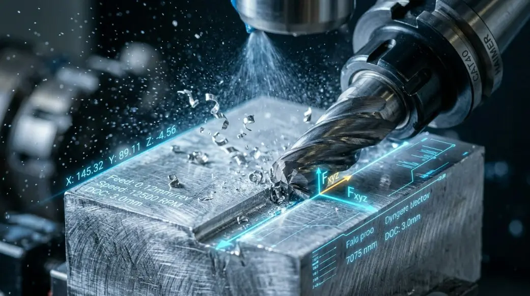
- Dynamic adjustment of tool travel path to counteract real-time tool tip abrasion and spindle thermal expansion.
Three independent compensation modules operate simultaneously inside the machine control software stack to address separate error sources. Geometric error compensation corrects inherent machine tool deviations including guide rail bending and spindle runout by pre-calibrated coordinate offset databases stored in the CNC system memory. Thermal error compensation relies on distributed temperature sensors placed across spindle, ball screw and machine frame assemblies to calculate thermal deformation displacement and adjust axis travel coordinates millisecond by millisecond.
Tool wear compensation continuously accumulates dimensional deviation data from each cutting pass, gradually modifying cutting path offsets as cutting edges erode over thousands of cutting strokes. The three complementary correction layers work in tandem to hold final part feature deviations within defined micron tolerance bands even during multi-hour non-stop manufacturing shifts. Long-term production statistics confirm finished component qualification rates above 99.5% when all three compensation systems are fully activated during machining cycles.
4. Two Categories Of Ultra-Precision Production Equipment
Two core machine tool models form the full production equipment lineup for complete ultra-precision component manufacturing, covering complex 3D cavity milling and rotary turning-milling composite parts respectively. Each equipment type carries unique drive system, control software and accuracy specifications tailored to distinct component feature requirements.
4.1 JDSGT400 Linear Motor Three-Axis Machining Center
| Parameter Category | Specific Technical Details |
|---|---|
| Core Positioning | Sub-micron ultra-precision processing for optical mold and semiconductor structural parts |
| Drive Architecture | Dual linear motor three-axis full direct drive system |
| Key Precision Index | Repeat positioning accuracy 0.8 µm; hole position tolerance <1µm within 100mm travel |
| Control Platform | Self-developed JD60 high-precision servo CNC system |
| Core Processing Advantage | Direct drive eliminates ball screw backlash, delivers functional-grade finished surfaces without secondary polishing |
| Primary Application Range | Precision optical molds, semiconductor hardware, medical micro structural parts |
4.2 GENOS L2000-e Turning Milling Composite Lathe
| Parameter Category | Specific Technical Details |
|---|---|
| Core Positioning | High-rigidity multi-axis turning and milling integrated cutting |
| Axis Configuration | Three main axes plus independent C auxiliary rotation axis |
| Processing Boundaries | Max turning diameter Φ200mm, maximum workpiece length 380mm |
| Spindle Performance | 5000 rated rpm, 15/11kW main drive motor power |
| Tool Storage | V12 twelve-station VDI precision servo turret |
| Motion Speed | X axis 25m/min, Z axis 30m/min rapid traverse velocity |
| Secondary Power Spindle | M axis auxiliary spindle rated 6000rpm for side feature milling |
| Control System | OSP-P300LA-e dedicated turning CNC controller |
The linear motor machining center targets planar, cavity and micro-hole ultra-precision features common to optical and semiconductor hardware, while the composite turning lathe specializes in rotary symmetrical components with complex lateral milling structures typical of medical implant parts. The paired equipment layout covers all mainstream precision part geometries without outsourcing secondary processing steps, maintaining unified process standards from blank clamping to finished component unloading inside the constant temperature production environment.
5. Standardized Composite Machining Production Flow
Multi-process composite cutting workflows integrate turning, milling, grinding and boring steps inside a unified manufacturing pipeline to eliminate repeated clamping errors that arise from transferring workpieces between separate machine tools. Every standardized production sequence follows fixed sequential steps to lock in consistent geometric accuracy across every production batch.
- Raw blank incoming inspection: Hardness, flatness and dimensional pre-measurement before temperature soaking cycle.
- 24-hour constant temperature pre-conditioning inside workshop storage cabinets to balance blank thermal state.
- Precision fixture clamping with zero-backlash positioning jigs to eliminate clamping offset.
- Program loading and pre-run machine self-calibration including probe offset detection.
- Primary rough cutting to remove excess material with moderate cutting speed to avoid thermal shock.
- Semi-finish cutting with partial error compensation activation to reduce feature deviation.
- Final finish machining with full three-layer real-time error compensation enabled.
- In-situ laser coordinate scanning to record finished feature dimensional data.
- Unloading and transfer to precision inspection station for full geometric tolerance verification.
- Surface cleaning and anti-oxidation packaging for qualified finished components.
Repeated clamping between separate machines introduces cumulative positioning deviation, often exceeding the total allowed tolerance band for ultra-precision parts. Composite single-setup machining eliminates multiple re-fixturing steps, retaining the original coordinate reference frame from blank to finished part and drastically reducing geometric tolerance drift across complex multi-feature components.
6. High-End Industry Application Fields For Precision Components
The micron-level dimensional stability delivered by controlled ultra-precision cutting makes manufactured parts essential hardware for multiple strict-tolerance advanced industrial sectors, each with distinct tolerance priorities for finished components.
- Optical Industry: Lens molds, sensor housing, micro prism fixtures requiring ultra-low surface roughness
- Medical Device Field: Surgical instrument hardware, implant structural components with biocompatible finish standards
- Semiconductor Manufacturing: Wafer transfer jigs, micro positioning mechanical assemblies
- Metrology Instrumentation: Calibration standard fixtures, precision gauge core structural parts
- Aerospace Auxiliary Hardware: Miniature actuation components with strict weight and tolerance limits
- Lab Analytical Equipment: Micro fluid channel metal substrates for testing instruments
Each vertical industry imposes unique manufacturing constraints: medical components require burr-free surfaces to avoid tissue irritation, optical molds demand mirror-grade surface finish without micro-scratches, and semiconductor jigs maintain ultra-stable dimensional consistency under repeated thermal cycling during chip production. The unified multi-process technical framework of Precision NC Machining adapts seamlessly to all these specialized finishing and tolerance requirements without separate custom manufacturing workflows for individual sectors.
7. Technical FAQ For Precision Manufacturing Engineers
8. Long-Term Batch Consistency Value Of Controlled Machining
Systematic environmental control, multi-layer error correction and composite single-setup cutting create sustained long-term manufacturing advantages for high-end component supply chains, focused entirely on production stability and finished part conformity without reference to cost or revenue metrics.
First, unified process control eliminates batch-to-batch dimensional fluctuation that plagues conventional machining facilities without constant temperature infrastructure. Consistent tolerance performance ensures downstream assembly lines operate without frequent part sorting and rework, streamlining the full component integration workflow for optical, medical and semiconductor device manufacturers.
Second, integrated real-time error compensation reduces manual operator intervention during extended production shifts, minimizing human-induced dimensional deviations that appear when technicians manually adjust machine offsets to counteract thermal drift or tool wear. Automated correction logic maintains uniform cutting parameters 24 hours a day for continuous manufacturing runs.
Third, single-setup composite cutting removes multiple workpiece transfer and re-clamping steps, lowering the risk of surface scratching, edge burrs and geometric offset damage during inter-machine handling. Finished components exit the production line with complete compliance to all drawing geometric and surface specifications, reducing scrap volume across long-term manufacturing schedules.
9. Professional Ultra-Precision Manufacturing Cooperation Channel
Shenzhen Sanluo Precision Technology Co., Ltd. operates a full constant temperature ultra-precision manufacturing base equipped with linear motor machining centers and composite turning-milling equipment, delivering customized precision component manufacturing services for optical, medical, metrology and semiconductor industrial clients globally. All production equipment undergoes daily calibration, and finished components pass full coordinate measuring machine inspection before release. Engineering teams provide complete technical drawing evaluation and process planning support for complex high-tolerance part projects.
Product designers, industrial engineering managers and component procurement specialists requiring complete equipment parameter documents, process flow blueprints and technical capability consultation may submit project inquiries through the official dedicated service portal.