
1. The Precision Mandate: Why Scale Demands a New Paradigm
The relentless miniaturization of mechanical systems across industries has placed unprecedented demands on manufacturing processes. Components that once measured in millimeters are now specified in microns, and the functional performance of entire assemblies often hinges on the geometric fidelity of a single micro-shaft. In this context, Micro Shaft Parts Super Precision Turning emerges not as an incremental improvement but as a fundamental enabler of next-generation engineering.
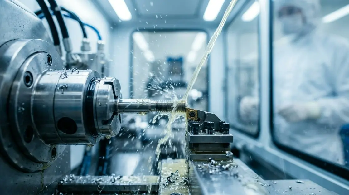
Traditional turning operations, while effective for macro-scale components, encounter severe limitations when workpiece diameters shrink below 1 mm. The physics of cutting changes dramatically: cutting forces that are negligible at large scales become dominant error sources, thermal expansion that is manageable becomes critical, and tool wear that is predictable becomes erratic. Super precision turning addresses these challenges through a combination of ultra-stiff machine architectures, advanced tool materials, and meticulously optimized process parameters.
The economic and performance stakes are substantial. A micro-shaft that deviates from its specified diameter by even 2 μm can render an entire subassembly non-functional. In medical devices, such deviations may compromise sterility or mechanical reliability. In aerospace applications, they can affect the balance and longevity of high-speed rotating systems. The precision turning process has therefore attracted enormous interest in the standardized and mass production of micro-shafts because it produces more efficiency compared with alternative methods such as electrical-discharge machining or electrochemical machining.
What distinguishes super precision turning from conventional precision machining is not merely the achievement of tight tolerances but the repeatability with which those tolerances are maintained across production runs. This repeatability is the product of holistic process control—encompassing machine calibration, environmental stabilization, tool condition monitoring, and real-time error compensation. When these elements are integrated effectively, the method delivers components that meet the most exacting specifications with remarkable consistency.
2. Core Principles of Super Precision Turning for Micro Shafts
At its essence, super precision turning for micro-shafts is governed by the same kinematic principles as conventional turning: a rotating workpiece is shaped by a controlled cutting tool that traverses along the axis of rotation. However, the implementation of these principles at micro-scale demands a fundamentally different approach to every aspect of the process.
2.1. Cutting Force Management
Cutting forces in micro-turning are proportionally larger relative to workpiece stiffness compared with macro-turning. A shaft with a diameter of 100 μm and a length of 5 mm has a length-to-diameter ratio of 50:1, making it highly susceptible to deflection under even modest radial forces. Research has demonstrated that dimensional error in micro-shafts with large length-diameter ratios can be reduced by 90% through appropriate error compensation strategies. This underscores the critical importance of force management in achieving super precision outcomes.
One particularly effective approach is thrust force-free turning, where the tool approach angle and depth of cut are configured such that the resultant thrust force approaches zero. This minimizes workpiece deflection and enables the production of shafts with straightness errors below 0.5 μm over a 10 mm length. Combining this with high-pressure coolant delivery and advanced tool coatings further reduces friction and built-up edge formation, which are common sources of surface roughness in micro-turning.
2.2. Thermal Stability and Error Compensation
Thermal expansion is another critical factor. Even a temperature rise of 1 °C can cause a 100 μm steel shaft to expand by approximately 1.2 μm—a significant fraction of the total tolerance budget. To counteract this, modern super precision turning centers incorporate temperature-controlled environments, spindle cooling systems, and thermal displacement sensors that feed back to the CNC controller. Real-time compensation algorithms adjust tool position based on measured thermal drift, ensuring that the final part dimensions remain within specification.
Furthermore, the use of air-bearing spindles and hydrostatic guideways eliminates mechanical contact friction, which both reduces heat generation and improves motion smoothness. These machine elements, combined with active vibration damping, create a stable cutting zone that is essential for achieving surface roughness values of Ra < 0.05 μm on micro-shafts. The integration of these principles into a single platform is what defines the state-of-the-art in Micro Shaft Parts Super Precision Turning.
3. Machine Architecture and Tooling Requirements
The machine tool used for super precision micro-turning is fundamentally different from a standard CNC lathe. It must provide sub-micron positioning resolution, minimal thermal growth, and exceptional static and dynamic stiffness. Key architectural features include:
- Granite or polymer concrete base – provides high damping and thermal inertia, isolating the work zone from floor vibrations.
- Linear motor drives – eliminate backlash and friction, enabling acceleration rates of up to 2 g and positioning repeatability of ±0.1 μm.
- Hydrostatic or aerostatic bearings – support both spindle and slideways with near-zero friction and excellent radial/axial stiffness.
- High-resolution encoders – typically laser interferometer or glass scale types with 0.01 μm resolution for closed-loop feedback.
- Tool post with quick-change capability – accommodates diamond, CBN, or coated carbide inserts with edge radii as small as 2 μm.
Tooling selection is equally critical. For super precision turning, single-crystal diamond tools are often preferred for non-ferrous materials due to their extreme hardness and low coefficient of friction. For ferrous alloys, polycrystalline cubic boron nitride (PCBN) or ceramic inserts are used, though they require more careful edge preparation to avoid micro-chipping. The tool nose radius typically ranges from 0.05 mm to 0.2 mm, depending on the desired surface finish and the aspect ratio of the shaft.
Additionally, tool wear monitoring is indispensable. Even 1 μm of flank wear can alter the effective cutting geometry and degrade surface quality. Modern machines integrate acoustic emission sensors or force dynamometers to detect wear progression and trigger tool changes automatically, ensuring that every part produced meets the super precision criteria.
4. Material Selection and Machinability
Not all materials are equally suited for super precision micro-turning. The machinability of a material determines the achievable surface finish, tool life, and dimensional stability. Commonly processed materials include:
| Material Group | Typical Alloys | Machinability Rating | Key Considerations |
|---|---|---|---|
| Aluminium alloys | 6061, 7075, 2024 | Excellent | Low cutting forces, good surface finish; prone to built‑up edge at low speeds. |
| Stainless steels | 304, 316, 17‑4PH | Moderate | High work hardening; requires rigid setup and sharp tools. |
| Titanium alloys | Ti‑6Al‑4V, Ti‑5Al‑2.5Sn | Difficult | Low thermal conductivity; heat accumulation may affect accuracy. |
| Brass / copper | C360, C110, beryllium copper | Very good | Excellent surface finish; chip control is straightforward. |
| Engineering plastics | PEEK, PTFE, Ultem | Good | Low cutting temperatures; but thermal expansion is high. |
For each material, the cutting parameters—speed, feed, depth of cut—must be carefully tuned. For example, aluminium alloys can be turned at speeds up to 500 m/min with diamond tools, while titanium requires speeds below 80 m/min to avoid excessive tool wear. The selection of coolant type and delivery method also varies; oil-based coolants are preferred for stainless steels to reduce friction, while water-miscible fluids are common for aluminium to improve heat dissipation.
In recent years, the use of cryogenic cooling (liquid nitrogen) has gained traction for difficult-to-machine materials, as it reduces cutting temperatures and improves tool life without introducing thermal distortion. This approach, though costly, has enabled super precision turning of hardened steels (up to 60 HRC) with surface finishes comparable to grinding.
5. Process Parameters and Their Influence on Quality
The interaction between cutting speed, feed rate, and depth of cut defines the quality of the finished micro-shaft. Each parameter has a distinct effect on surface roughness, roundness, and residual stress.
- Cutting speed (Vc) – Higher speeds generally reduce built‑up edge and produce smoother surfaces, but they also increase tool wear and thermal loading. Optimal speed is typically found at the upper limit of the tool’s recommended range.
- Feed rate (f) – The feed per revolution directly influences the theoretical surface roughness (Ra ≈ f² / (8·r) for a given nose radius). A lower feed improves finish but reduces productivity. For super precision, feeds are often set between 1 μm/rev and 5 μm/rev.
- Depth of cut (ap) – The depth should be at least twice the nose radius to ensure stable cutting, but excessive depth increases radial forces and deflection. For micro-shafts, depths of 10 μm to 50 μm are common.
To illustrate the combined effect, consider a brass micro-shaft (diameter 0.5 mm) turned with a diamond tool (nose radius 0.05 mm). Using Vc = 300 m/min, f = 2 μm/rev, and ap = 20 μm, the theoretical Ra is about 0.01 μm, which is well within the super precision range. However, if the feed is doubled to 4 μm/rev, the Ra increases to 0.04 μm—still acceptable but nearing the limit for critical applications.
In practice, the selection of parameters must also account for machine dynamics. Unstable cutting conditions (chatter) can occur at certain spindle speeds and feed combinations, leaving visible vibration marks on the shaft surface. Advanced process monitoring systems use accelerometers to detect chatter and automatically adjust the spindle speed or feed rate to suppress it, ensuring a consistent surface quality throughout the production batch.
6. Quality Assurance: Measurement and Metrology
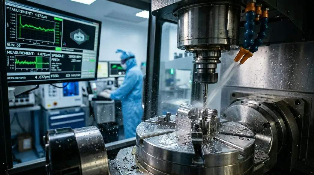
Verifying that a micro-shaft meets the super precision specification requires measurement instruments capable of nanometer resolution. The following technologies are commonly employed:
- Interferometric length measurement – Uses laser interferometers to measure diameter and length with accuracy better than ±0.1 μm.
- Roundness measurement – Performed with a precision spindle and an LVDT probe; roundness errors below 0.2 μm are achievable.
- Surface profilometry – Contact or non‑contact (white light interferometry) profilers measure Ra and Rz values over the shaft surface.
- Coordinate measuring machines (CMM) – For complex micro‑shafts with multiple features, a CMM with a stylus diameter of 0.5 mm or less can inspect form and position tolerances.
- Optical comparators and vision systems – Provide fast, non‑contact dimensional checks for high‑volume production.
Beyond dimensional inspection, material integrity is assessed through hardness testing (micro‑Vickers) and residual stress measurement (X‑ray diffraction). These are particularly important for shafts that will undergo subsequent heat treatment or assembly with interference fits. Statistical process control (SPC) charts are maintained for critical parameters, enabling early detection of process drift and allowing corrective actions before any non‑conforming parts are produced.
It is worth noting that the measurement environment must be as controlled as the machining environment. Temperature fluctuations, air currents, and floor vibrations can all introduce measurement errors. Therefore, metrology labs are typically located in clean rooms with temperature stability of ±0.1 °C and vibration isolation tables.
7. Applications Across Critical Industries
The demand for Micro Shaft Parts Super Precision Turning is driven by several high‑value sectors where miniaturisation and precision are non‑negotiable.
- Medical devices – Guide wires, catheter components, and surgical micro‑drills require shafts with exceptional straightness and smooth surfaces to minimise tissue trauma. Stainless steel and nitinol are common materials, and the process ensures that surface roughness does not promote bacterial adhesion.
- Aerospace – Fuel metering valves, hydraulic actuators, and gyroscope gimbals contain micro‑shafts that must withstand extreme temperatures and pressures. Super precision turning of Inconel and titanium alloys provides the necessary fatigue resistance and dimensional stability.
- Automotive – Fuel injection systems for diesel and gasoline engines use micro‑shafts that control metering orifices with micron‑level accuracy. The process reduces friction and wear, contributing to improved fuel economy and lower emissions.
- Electronics – Miniature motors for hard disk drives, camera stabilisers, and drone gimbals rely on micro‑shafts with minimal runout to maintain rotational accuracy. Copper‑beryllium and hardened steel are often chosen for their electrical and mechanical properties.
- Optical and photonics – Fibre‑optic alignment sleeves and micro‑positioning stages contain shafts that guide light with sub‑micron precision. The turning process produces surfaces that are free from scratches and contaminants, ensuring low optical loss.
In each of these applications, the ability to consistently produce shafts with diameters down to 0.1 mm and length‑to‑diameter ratios exceeding 30:1 is a competitive differentiator. The process also enables the production of complex features such as tapers, grooves, and threads on the same micro‑shaft, reducing the need for secondary operations.
8. Persistent Challenges and Mitigation Strategies
Despite advances, Micro Shaft Parts Super Precision Turning faces several inherent challenges that require ongoing attention.
- Workpiece deflection – As discussed, slender shafts bend under cutting forces. Mitigation includes using tailstock support (live centres), reducing depth of cut, and employing counter‑rotating tool paths to balance forces.
- Tool wear – Even diamond tools wear over time, affecting surface finish. Regular tool inspection and in‑process wear monitoring are essential. Coated tools and advanced lubricants extend tool life.
- Thermal distortion – Heat generated during cutting can cause expansion of both the workpiece and the machine structure. Coolant application, air‑cutting techniques, and machine warm‑up routines help maintain thermal equilibrium.
- Burr formation – At the entry and exit of cuts, small burrs can compromise shaft function. Deburring processes such as electrochemical deburring or abrasive flow machining are often added as post‑process steps.
- Surface contamination – Fine particles or coolant residues can affect surface quality. Ultra‑clean machining environments and post‑process cleaning (e.g., ultrasonic washing) are standard practices.
To address these challenges holistically, many manufacturers adopt a “closed‑loop” approach where process data (forces, temperature, vibration) are continuously collected and fed back to a machine learning model that predicts optimal parameters for each new batch. This data‑driven strategy has demonstrated improvements in first‑pass yield from below 80% to over 95% for complex micro‑shaft geometries.
9. Frequently Asked Questions
Shenzhen Sanluo Precision Technology Co., Ltd. is dedicated to delivering micro‑shafts that meet the most stringent super precision requirements. Our manufacturing expertise, combined with rigorous quality systems, ensures every part performs exactly as designed.
Connect with our engineering team