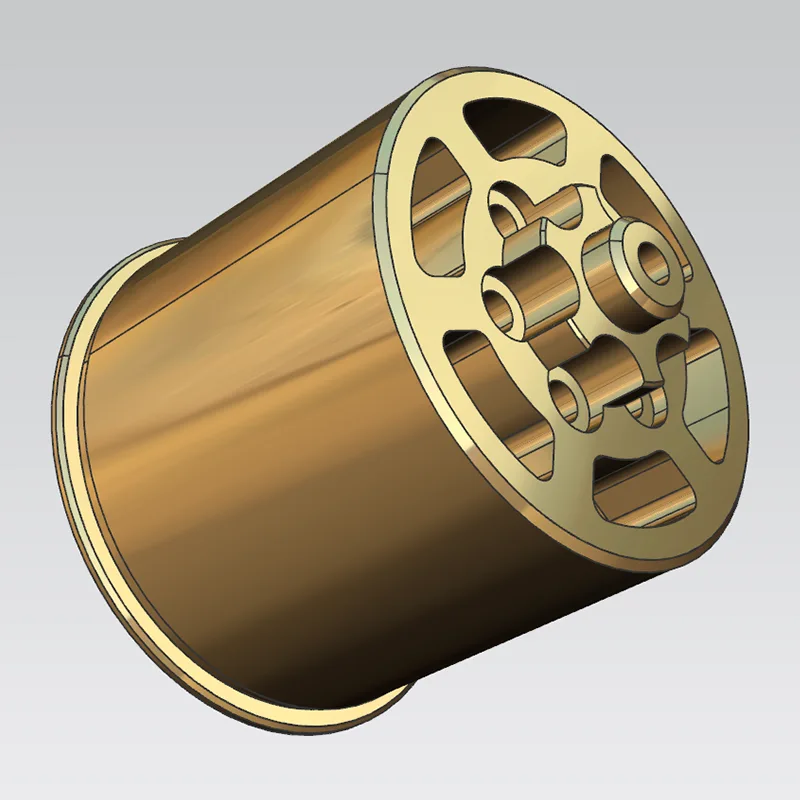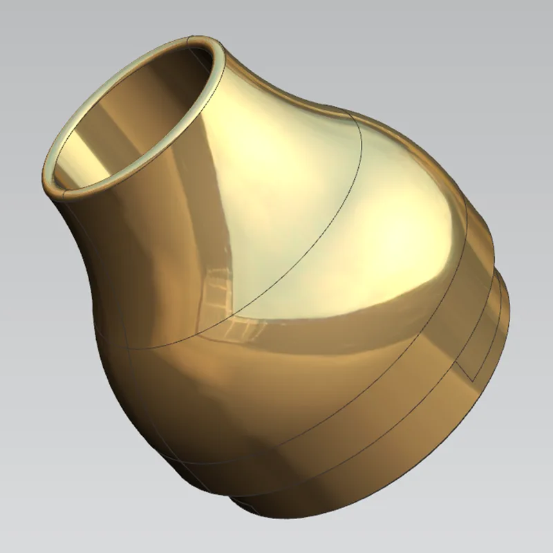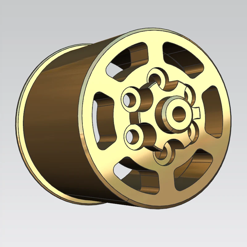

CNC micro milling is the controlled removal of material with very small rotary cutters, high-speed spindles, and precision machine motion. Use it when a part needs miniature slots, channels, pockets, contours, or complex surfaces cut directly into metal or engineering plastic. It is especially useful when those features must retain machined geometry rather than the heat-affected edges of laser processing or the electrically conductive material requirement of EDM.
Micro milling is not simply conventional milling with a smaller end mill. Cutter runout, spindle behavior, chip evacuation, workholding, toolpath control, and inspection all become more influential as features shrink. A capable supplier must control the complete process, not just own a machine with an impressive positioning specification.
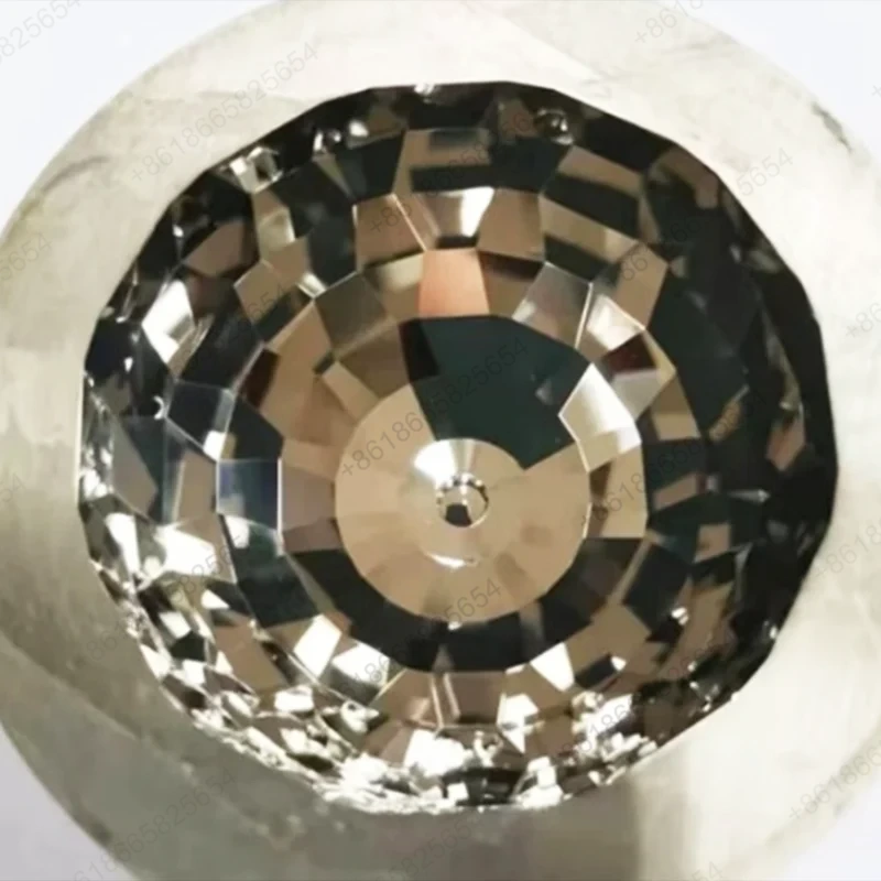
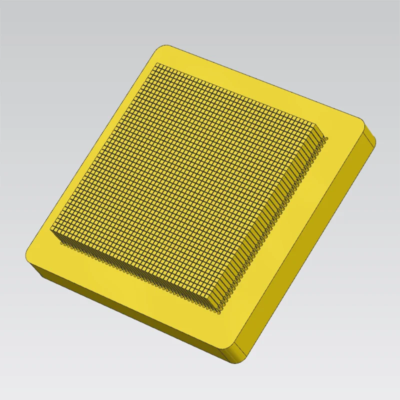
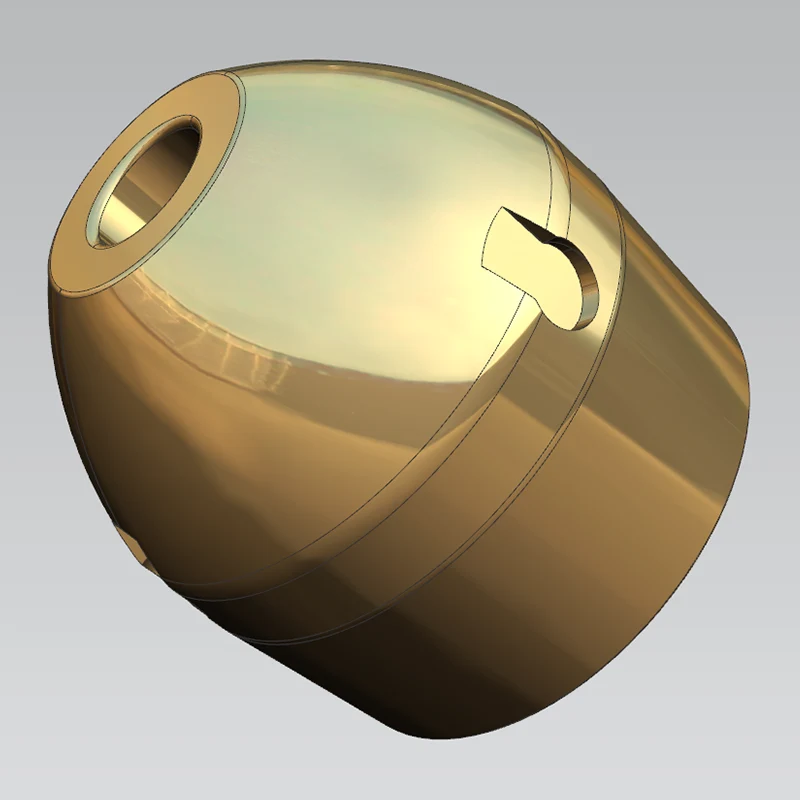
The process makes sense when the specified material and machined surface are part of the final component. Typical work includes precision mold inserts, electronic-device housings, medical equipment components, aerospace parts, semiconductor equipment, and optical communication hardware.
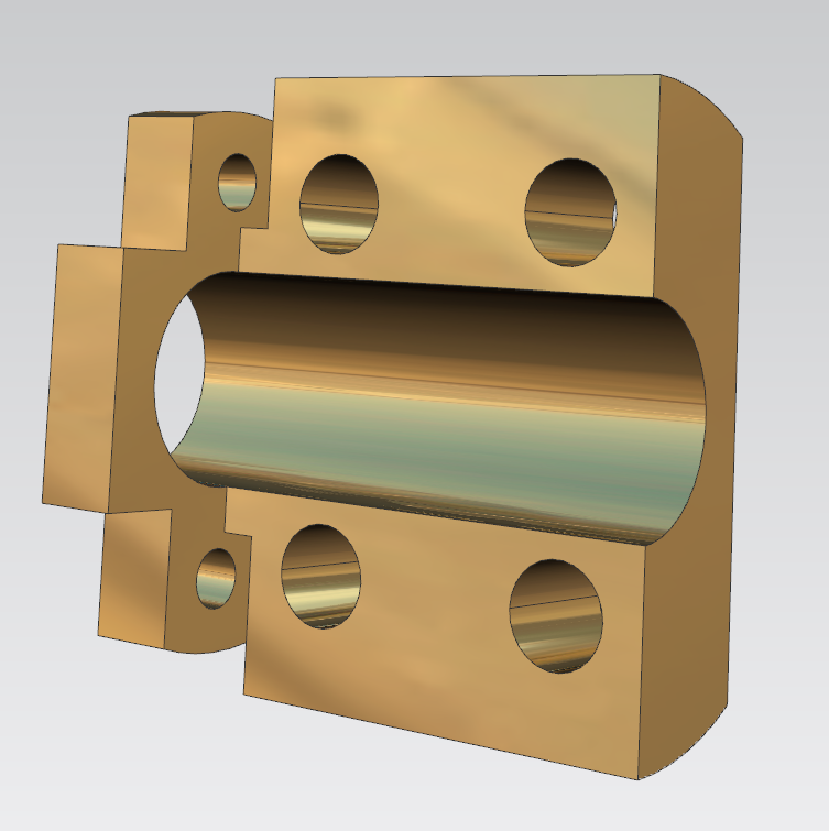
A custom CNC micro milling service is particularly useful for mixed geometry: a part may combine ordinary mounting faces with a tiny cavity, narrow channel, or detailed 3D contour. Keeping those features in one controlled machining workflow can reduce alignment errors between operations.
Micro milling also supports prototypes because it avoids dedicated molding tooling. That does not make every prototype cheap. Small cutters have limited material-removal rates, and intricate toolpaths may require substantial programming, inspection, and setup time.
Small tools need suitable spindle speed to produce a clean cutting action at their tiny diameter. Sanluo Precision lists micro cutters down to 0.04 mm and spindle ranges from 20,000 to 100,000 rpm, with the available range depending on the machine. Those figures describe the equipment envelope; they do not mean every tool, material, and feature should run at maximum speed.
Accuracy depends heavily on low runout. Even slight eccentricity can overload one flute, produce uneven tool wear, enlarge a slot, or snap a fragile cutter. The process plan must also manage chips and heat. Recut chips scratch cavity walls, while heat concentrated in titanium alloys or thin sections can shorten tool life and distort the workpiece. Stable fixturing matters, but excessive clamping pressure can deform the same delicate part the process is meant to protect.
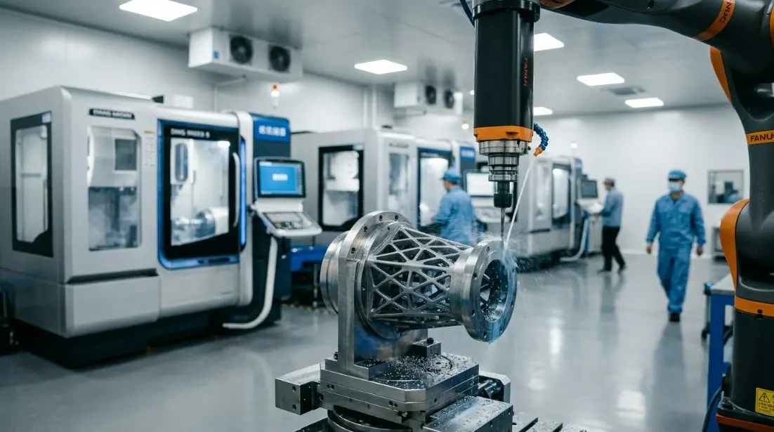
Three-axis machining is usually the practical choice for open pockets, planar patterns, and features accessible from one direction. Four-axis motion helps place radial features or rotate a component without repeated manual setups. Five-axis micro milling becomes valuable for undercut access, angled walls, compound surfaces, and parts whose critical features must maintain their relationship across several faces.
Simulation can check tool reach, holder clearance, rotary-axis motion, and remaining stock before cutting begins. AI-assisted systems may also flag unusual toolpath conditions or collision patterns, but they are not substitutes for accurate tool, holder, fixture, and machine models. Bad setup data produces reassuring but unreliable simulation.
A tolerance should be assigned according to function and geometry. A shallow pocket in aluminum, a deep slot in hardened steel, and a thin-walled titanium feature will not hold the same practical tolerance merely because they run on the same machine.
Tool diameter, aspect ratio, material hardness, burr formation, thermal stability, tool wear, datum strategy, and inspection access all influence the result. Tightening every dimension can raise cost without improving performance. Identify the sealing surfaces, optical interfaces, mating profiles, and true positional relationships that carry functional risk; leave noncritical dimensions at sensible commercial limits.
Positioning accuracy describes how closely an axis reaches a commanded location. Repeatability describes how consistently it returns there. Neither value automatically predicts the finished part.
Profile tolerance controls how closely a surface follows its defined contour. Achievable part tolerance includes more variables: cutter deflection, runout, workholding, material movement, tool wear, thermal conditions, and measurement uncertainty. Buyers often compare machine specifications while overlooking datum transfer between setups—the source of many feature-to-feature errors on complex parts.
Sanluo Precision publishes a profile tolerance of ±0.005 mm and surface roughness of Ra 0.2–0.8 μm for its high-precision micro milling capabilities. These are useful screening figures, but feasibility still depends on the selected machine, material, feature size, depth, accessibility, and inspection method.
A fine roughness result on an accessible aluminum surface does not establish the same finish at the bottom of a deep steel cavity. Ask which surfaces and geometries the quoted values cover, and whether tolerance and finish can be achieved simultaneously.
| Process | Best fit | Main constraint |
|---|---|---|
| Micro milling | 3D contours, pockets, channels, and defined surfaces in metals or plastics | Tool access, cutter deflection, burrs, and internal corner radius |
| Micro EDM | Fine features in conductive materials, especially hard alloys and sharp cavity details | Conductive materials only; electrode or wire access and slower removal can matter |
| Laser machining | Very small cuts, holes, and patterns with no cutting force | Heat-affected zones, taper, recast, or edge condition may be unacceptable |
| Conventional CNC | Larger features, faster stock removal, and less delicate geometry | Standard tooling and spindle behavior may not suit miniature details |
Hybrid processing is often the better answer. Conventional milling can remove bulk stock before micro milling finishes critical details; EDM or grinding may handle features that a tiny rotating cutter cannot reach efficiently.
Strong candidates include precision cavities, miniature fluid channels, mold details, electronic features, and complex 3D surfaces that require controlled geometry. Sanluo Precision machines steel, aluminum, copper, titanium alloy, engineering plastics, and specialized materials, but each presents different problems. Copper can burr, engineering plastics can move with heat or clamping, and titanium concentrates heat near the cutting edge.
Risk rises with deep narrow slots, tall thin walls, inaccessible internal corners, weakly supported features, and dimensions that leave no practical allowance for tool radius. Tiny flat-bottomed internal corners are a common drawing mistake: a rotary cutter always leaves a radius unless another process removes it. Very high aspect-ratio features may also require several passes, special tooling, or a process change.
Start with a fully dimensioned model, material specification, critical datums, surface-finish callouts, and expected quantity. Mark the few features that control function. The supplier can then select among 3-axis, 4-axis, and 5-axis equipment rather than forcing the job onto a machine chosen from a generic capability chart.
Ask which machine, spindle range, cutter size, setup count, and inspection method will be used. For very small features, a standard touch probe may not be suitable; optical or other specialized metrology may be required. Sample evidence should come from comparable material, depth, geometry, and tolerance—not an unrelated demonstration part.
For repeat production, confirm how tool wear, replacement intervals, fixture location, burr control, and inspection frequency will be managed. A prototype that depends on manual adjustment may not remain stable across a larger batch. The right choice is a supplier willing to tie every claim to the actual feature and equipment. Sanluo Precision’s published micro CNC machining service details provide a useful starting point; the purchase decision should follow an equipment-specific manufacturability review and an agreed inspection plan.
-