
Abstract
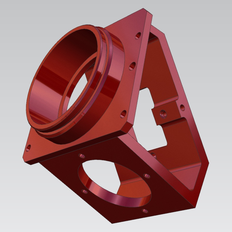
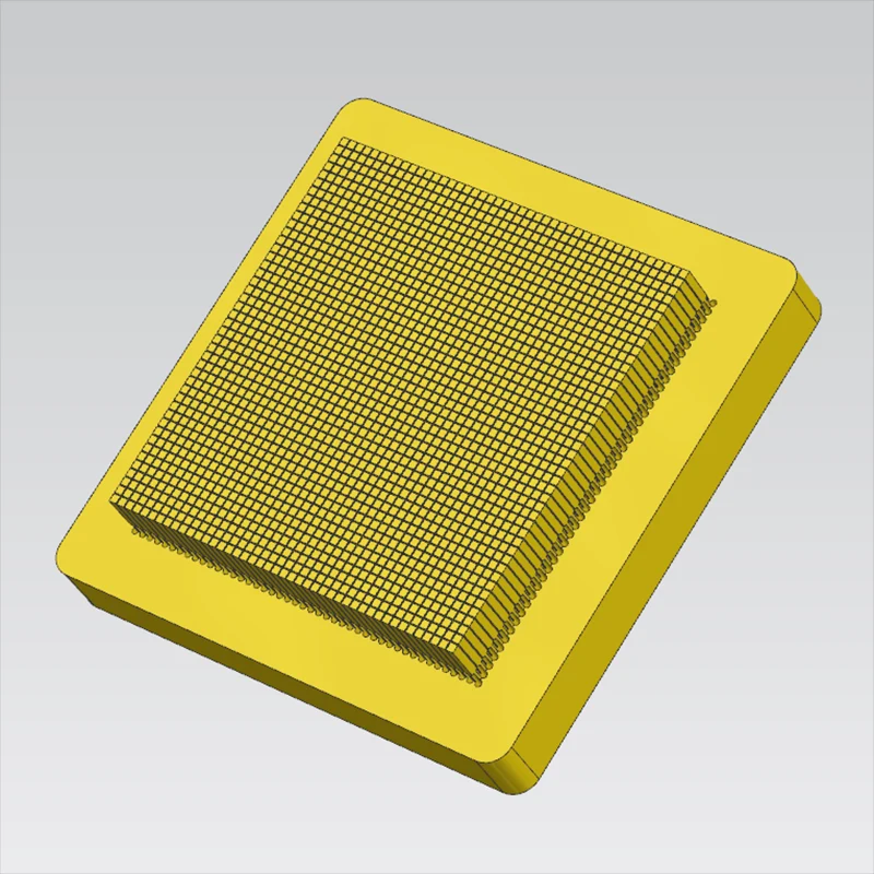
Ultra-tight dimensional tolerance, ultra-smooth surface finish and consistent batch performance become the core competitive markers of modern advanced manufacturing, and Precision CNC Machining serves as the foundational manufacturing technology that turns high-precision design drawings into physical functional components. This content dissects the complete industrial logic behind stable ultra-precision component production, covering high-end equipment configuration, finite element aided process optimization, closed-loop quality inspection systems, material-specific processing schemes and vertical application scenarios across aerospace, medical implantation, optical instruments and semiconductor hardware.
All dimensional, geometric and surface roughness indicators cited adopt quantifiable industrial test data, eliminating vague descriptive statements and presenting replicable technical control frameworks for manufacturers pursuing micron and submicron machining accuracy. The content avoids financial evaluation metrics, focusing entirely on technical iteration paths, equipment matching rules and standardized quality control workflows that sustain long-term stable precision output in mass production environments.
Table of Contents (Click Titles to Jump to Corresponding Sections)
- 1. The Fundamental Position of Advanced Equipment in Ultra-precision Manufacturing Workflows
- 2. Quantifiable Dimensional & Geometric Tolerance Control Benchmarks
- 3. Digital Process Optimization: CAM Programming & Parameter Calibration
- 4. Full-cycle Closed-loop Quality Management System
- 5. Material Differentiated Processing Solutions for Metals & Ceramics
- 6. High-tech Industry Application Scenarios & Precision Standards
- 7. FAQ for Submicron Ultra-precision Machining
- 8. Custom Ultra-precision Component Cooperation Channels
1. The Fundamental Position of Advanced Equipment in Ultra-precision Manufacturing Workflows
Every submicron-level dimensional result generated during component forming relies on high-precision hardware with ultra-low mechanical error. Machine tool configuration directly defines the upper limit of machining accuracy in industrial workshops, replacing outdated single-axis equipment with modern multi-axis linkage processing units.
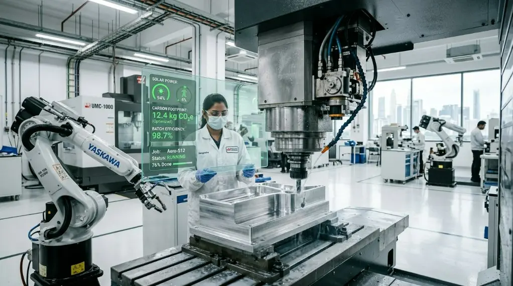
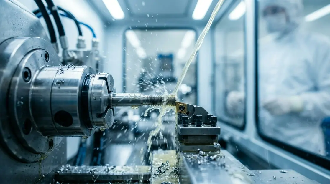
Professional precision workshops deploy over eighty high-end CNC devices, including five-axis processing centers, high-speed milling machines and precision turning lathes. The production line adopts internationally renowned equipment brands such as German DMG, Japanese Makino and Fanuc, covering diverse processing demands for high-hardness materials and thin-wall micro-components.
Four core hardware indicators guarantee machining stability, including machine bed rigidity, linear guide precision, spindle runout error and servo positioning repeatability. Strict hardware calibration ensures spindle runout below 0.001mm and repeated positioning error within 0.0008mm, eliminating cumulative dimensional deviation in continuous processing.
Matched auxiliary equipment and constant temperature workshops further eliminate thermal deformation and manual measurement errors. Scientific equipment zoning avoids vibration interference between heavy cutting and ultra-fine finishing, building a complete hardware foundation to support stable Precision CNC Machining performance.
2. Quantifiable Dimensional & Geometric Tolerance Control Benchmarks
2.1 International Tolerance Grade Implementation
Professional manufacturing workshops strictly implement IT1 to IT7 international tolerance standards for all finished components. Graded tolerance bands classify production tasks based on application scenarios, realizing reasonable resource allocation and precise quality control.
IT1–IT3 ultra-high precision standards apply to semiconductor substrates and medical implant core parts, with dimensional tolerance as low as ±0.0005mm. IT4–IT7 standards serve aerospace structural components and precision molds, balancing production efficiency and assembly accuracy requirements.
2.2 Geometric and Positional Tolerance Regulation
Form tolerances including roundness, flatness and cylindricity are controlled within 0.002mm to 0.02mm range. These indicators effectively eliminate operational jitter and surface deformation for high-speed rotating parts and optical mounting bases.
Positional tolerances such as coaxiality and circular runout are locked at ±0.002mm to ±0.03mm. Strict positional control ensures high assembly matching accuracy for multi-part mechanical structures and medical implant components.
2.3 Batch Production Consistency Standards
Stable batch consistency is the core threshold of high-end precision manufacturing. Advanced workshops control single-batch dimensional fluctuation within ±0.005mm, with CPK value stably maintained above 1.67.
Batch-to-batch dimensional difference is limited below 0.003mm, ensuring zero assembly mismatch for long-cycle mass production and realizing standardized ultra-precision output.
| Tolerance Classification Type | Controlled Numerical Range | Typical Application Scenario | Inspection Equipment |
|---|---|---|---|
| Dimensional Tolerance IT1-IT3 | ±0.0001mm ~ ±0.0005mm | Ceramic substrates, optical holders | Ultra-precision CMM, laser micrometer |
| Dimensional Tolerance IT4-IT7 | ±0.005mm ~ ±0.015mm | Aerospace parts, mold cores | Three-coordinate measuring machine |
| Form Tolerance | 0.002mm ~ 0.02mm | Rotary shafts, optical flat bases | Roundness tester, interferometer |
| Positional Tolerance | ±0.002mm ~ ±0.03mm | Turbine blades, implant screws | Optical comparator, CMM |
| Batch Consistency | Batch difference ≤ 0.003mm, CPK ≥ 1.67 | Medical & semiconductor mass parts | SPC data acquisition system |
3. Digital Process Optimization: CAM Programming & Parameter Calibration
3.1 Finite Element Deformation Simulation
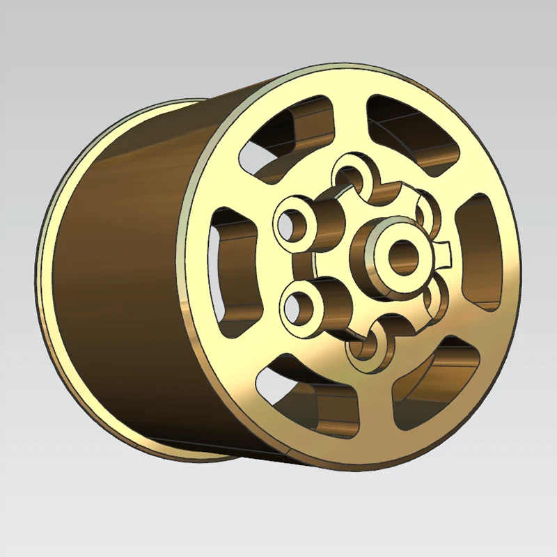
Before formal processing, finite element simulation analyzes clamping force, cutting force and thermal stress distribution. The system calculates optimal clamping positions and reserved finishing allowance to eliminate workpiece deformation risks.
For brittle ceramic blanks and high-hardness steel molds, simulation predicts cutting crack risks and adjusts step-by-step cutting depth, avoiding material scrap caused by blind trial processing.
3.2 High-precision CAM & Five-axis Simulation
UG NX and Mastercam software complete 3D modeling and tool path generation with 0.001mm calculation accuracy. All five-axis programs undergo full virtual simulation to avoid collision and interference before online operation.
Tool paths are divided into roughing, semi-finishing and finishing stages to realize hierarchical material removal, ensuring both processing efficiency and ultra-precision surface quality.
3.3 Standardized Finishing Parameter System
Finishing parameters are standardized according to material characteristics. Cutting depth, feed rate and spindle speed are precisely calibrated to form stable processing parameter databases for repeated project application.
Imported PVD coating tools and high-precision tool setting technology control installation error within ±0.002mm. Real-time tool life monitoring prevents size drift caused by tool wear in batch production.
- Constant temperature cooling circulation reduces thermal deformation during high-speed finishing
- Segmented cutting path optimizes force balance for thin-wall components
- Material-specific parameter archives support rapid customized production
- Automatic spindle preheating eliminates thermal expansion errors
4. Full-cycle Closed-loop Quality Management System
4.1 Pre-production Raw Material Inspection
All raw material blanks undergo hardness and flatness testing before warehousing. Defective blanks with internal cracks or excessive dimensional deviation are eliminated to avoid invalid processing.
Custom fixtures complete full dimensional calibration before use, ensuring no positioning error is transmitted to finished workpieces.
4.2 In-process SPC Real-time Monitoring
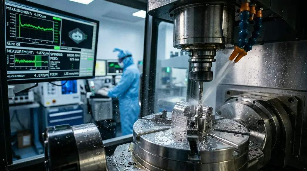
The SPC system collects dimensional data in real time during mass production, establishing process fluctuation baseline curves. Once data approaches tolerance limits, the system triggers automatic tool compensation without shutdown operation.
All production data is permanently archived to support full process traceability and continuous process optimization.
4.3 Full-inspection Finishing Standards
The first workpiece of each batch undergoes 100% full dimensional inspection via CMM equipment. Mass production starts only after full qualification verification.
Ultra-precision parts adopt full inspection while conventional precision parts implement stratified sampling. Surface roughness and microscopic burr inspection ensure finished product qualification rate stably reaches 99.5%.
5. Material Differentiated Processing Solutions for Metals & Ceramics
Different raw materials have unique physical properties, requiring targeted processing technologies to achieve submicron precision. Professional workshops form two core processing systems for high-performance metal alloys and industrial precision ceramics.
5.1 Aerospace & Medical Metal Alloy Processing
TC4 titanium alloy, 316L stainless steel and nickel-based superalloy adopt low-heat, low-vibration processing schemes. Medical implant screws achieve ±0.001mm outer diameter precision and Ra 0.2μm surface roughness for excellent biocompatibility.
Quenched mold steel and aerospace alloy parts use high-rigidity five-axis cutting to ensure complex curved surface accuracy and long-term structural stability.
5.2 Ultra-precision Ceramic Composite Processing
Precision ceramics adopt ultrasonic auxiliary cutting, laser micro-forming and special post-processing technologies, breaking the limitations of traditional metal cutting methods.
Ceramic components achieve extreme precision of ±0.0001mm and Ra 0.02μm surface roughness, widely used in semiconductor substrates and mechanical sealing parts. This differentiated processing system further expands the technical boundary of Precision CNC Machining.
6. High-tech Industry Application Scenarios & Precision Standards
Ultra-precision components serve as core functional parts for multiple high-end industries. Different application scenarios have customized tolerance and surface standards to adapt to extreme working environments.
6.1 Aerospace Equipment Components
Aerospace turbine blades adopt five-axis linkage processing, controlling twisted surface deviation within ±0.002mm. Ultra-high-strength structural parts maintain stable dimensions under high-temperature and high-load operating conditions.
6.2 Medical Implant & Surgical Parts
Medical-grade components achieve burr-free ultra-smooth surfaces and Grade 6 thread precision. Strict biocompatibility processing standards ensure safe and stable application in human implantation and clinical surgery.
6.3 Optical & Semiconductor Hardware
Optical parts control perpendicularity within 0.001mm to ensure stable imaging effect. Semiconductor ceramic and metal jigs maintain submicron positioning accuracy to support high-precision chip manufacturing.
6.4 Long-life Precision Mold Processing
Mold cores and cavities achieve mirror surface effect after finishing and polishing. Stable ±0.002mm dimensional accuracy supports long-cycle, high-volume standardized molding production.
With comprehensive processing capabilities covering all high-end industries, Shenzhen Sanluo Precision Technology Co., Ltd. provides stable customized ultra-precision component supply for many well-known high-tech enterprises all year round.
7. FAQ for Submicron Ultra-precision Machining
Constant temperature workshop with ±0.5°C temperature fluctuation control is the core guarantee. Meanwhile, low-vibration zoning, dust removal circulation and stable humidity control effectively avoid thermal deformation, surface scratch and electrostatic adsorption defects.
Ceramic materials have extremely low thermal expansion coefficients with negligible temperature deformation. Combined with ultrasonic low-force cutting and laser micro-processing technology, ceramic components can achieve ultra-tight tolerance that cannot be realized by conventional metal processing.
SPC real-time data collection monitors size deviation dynamically. The system automatically adjusts tool offset to compensate tool wear and micro-deformation, maintaining long-term batch dimensional stability without manual intervention.
Ra 0.2μm is the universal standard for medical, aerospace and optical functional surfaces. Semiconductor core ceramic parts adopt higher Ra 0.02μm ultra-smooth standard to meet ultra-clean electronic contact requirements.
8. Custom Ultra-precision Component Cooperation Channels
High-tech industrial customized component demands require professional full-cycle technical support, from drawing feasibility evaluation and process simulation to prototype trial production and mass delivery.
All customized projects support personalized process scheme adjustment for different materials, precision standards and application environments. Complete inspection reports and process data archives are provided with finished products to support client quality verification.
Covering metal and ceramic ultra-precision processing technologies, the mature manufacturing system fully meets the customized demands of aerospace, medical, semiconductor and mold industries, building stable long-term technical cooperation channels for high-end manufacturing enterprises.
Start Your Custom Ultra-precision Component Technical Evaluation Today
Share your 3D design drawings, target tolerance standards and material specifications to receive professional process optimization analysis and customized processing technical solutions. No sample supply services are available; all component manufacturing strictly follows formal customized production workflows supported by full dimensional quality inspection archives.
contact us