
A component can meet its drawing dimensions and still fail a development program. A thin instrument tube may spring after release from the fixture. A drilled passage may carry a burr into a fluid path. A bone screw thread may look acceptable until its mating behavior is checked. These are not minor shop-floor details; they are risks that can force a redesign, delay verification, or make prototype results impossible to repeat.
The short answer is that medical device precision machining reduces risk by identifying the feature most likely to fail, choosing a process around that risk, and defining inspection evidence before parts are cut. Tight tolerances matter, but they are only one part of the decision.
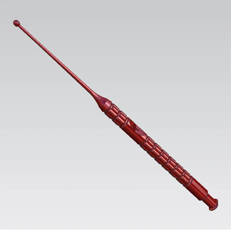
Buyers often start a supplier conversation with a tolerance callout. That is understandable, yet it can hide the real question: what could make this part unusable even if a few measured dimensions are in range? For a surgical instrument, it may be a burr, rough sliding surface, or loss of straightness. For an implant component, the concern may be the relationship between threads, a contoured surface, and a critical mating feature.
Good medical device precision machining services work backward from those functional risks. The machining sequence, workholding approach, finishing steps, and inspection plan should all answer the same question. This shifts development from “can the machine make it?” to “can the process repeatedly preserve the feature that makes the device work?”
That approach also prevents a common prototype mistake: approving a one-off part produced through excessive manual intervention, then discovering that the same result cannot be held as quantities rise. A feasible process is not necessarily the fastest one, and the lowest unit quote is not necessarily the lowest program cost.
Every drawing has a few features that drive the manufacturing risk. Find them before requesting quotes. Ask which dimension is datum-critical, which surface interfaces with another part or tissue, where material is least supported, and which feature cannot be reworked after a later operation. Those answers should influence the route sheet more than the total number of dimensions on the print.
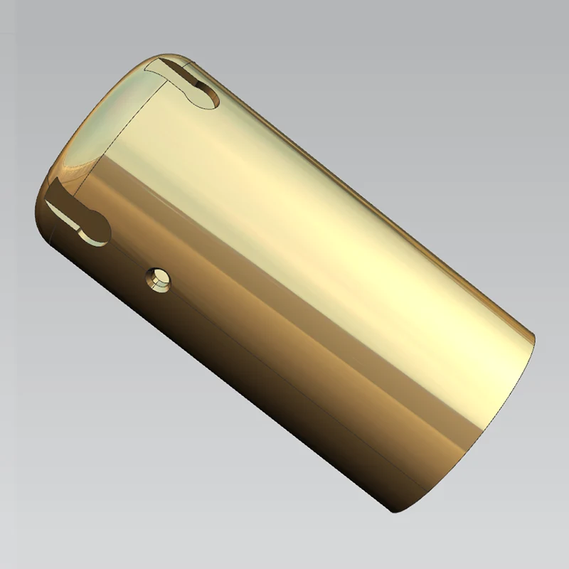
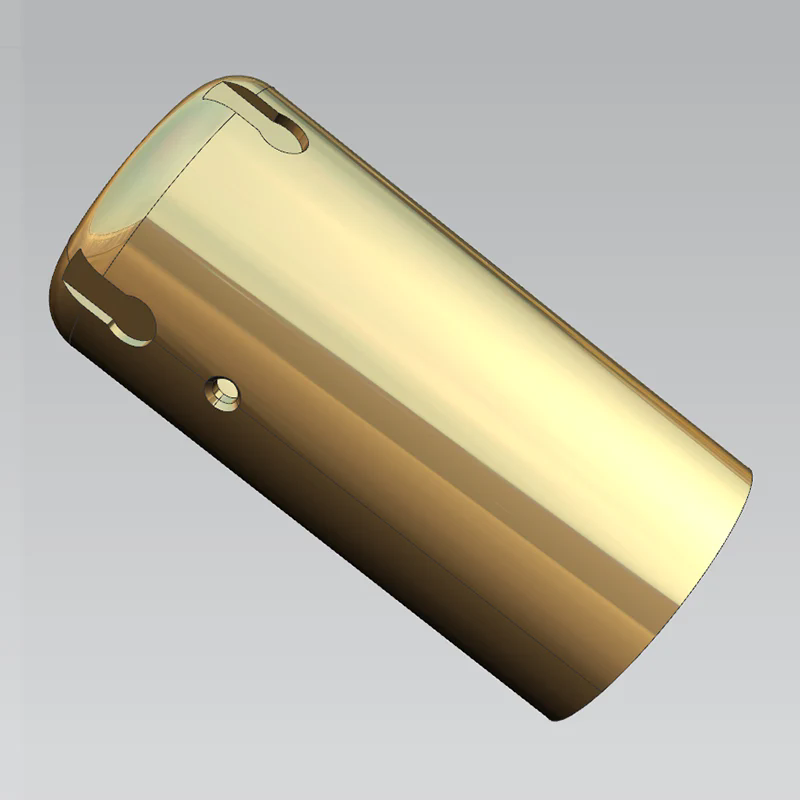
Slender geometries are vulnerable because cutting loads, heat, clamping force, and residual stress can move the part. The problem may not show up until the component is unclamped. A tube can become oval; a narrow wall can deflect during finishing; a long turned shaft can lose concentricity relative to features made in another setup.
Process choices such as staged material removal, support close to the cutting zone, carefully planned clamping, and finishing operations after roughing can reduce that exposure. The trade-off is real: added setups and more deliberate handling can increase lead time. Still, that is usually cheaper than chasing an unstable geometry with inspection sorting. For small, turned parts, Swiss machining is especially useful because the guide bushing supports stock near the tool, helping control deflection on long, small-diameter features. It is not an automatic answer, though. The part geometry, material form, surface requirements, and downstream operations still determine whether it is the right route.
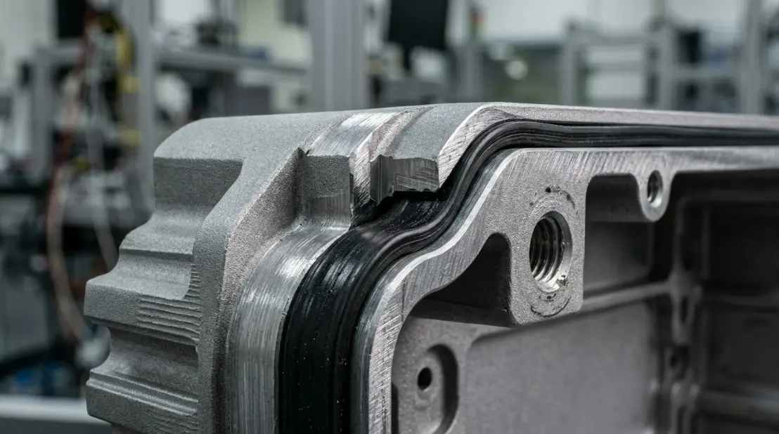
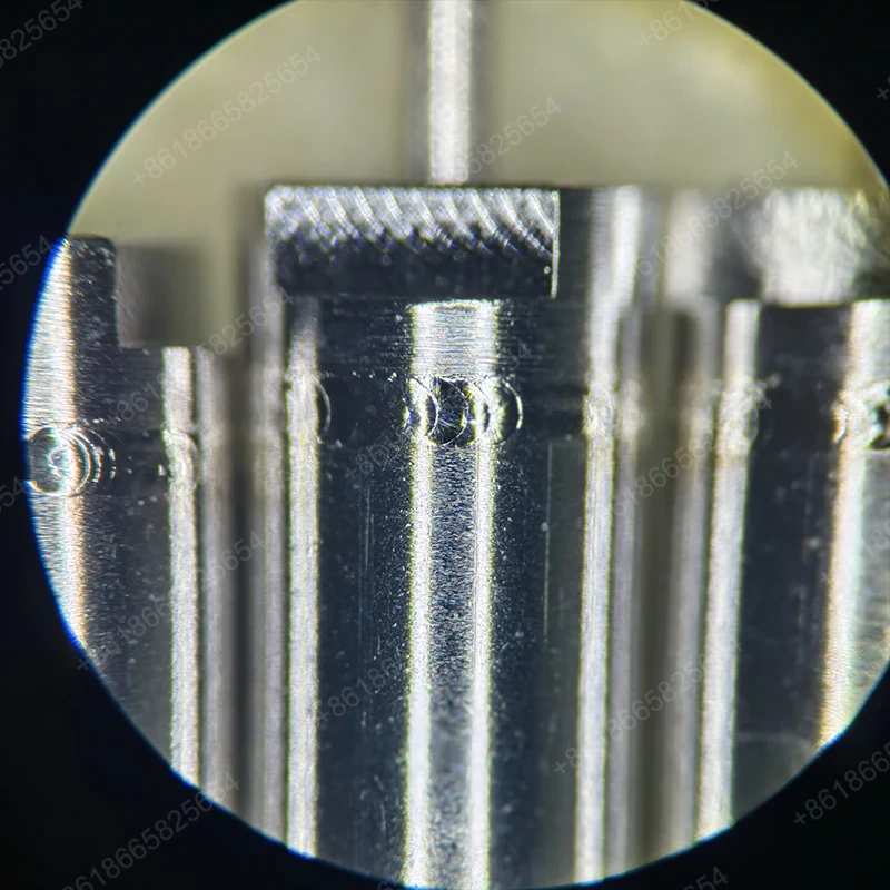
Small holes, slots, undercuts, and fine internal details create a different class of risk. Tool breakage is obvious. Burr formation, blocked passages, damaged edges, and uncertain measurement are often more costly because they can remain hidden until assembly or functional testing.
Micro machining, laser beam machining, EDM, or a combination of methods may be considered based on feature geometry and material response. The key is not simply achieving an opening of the requested size. You need agreement on acceptable edge condition, burr-control method, access for cleaning, and how the feature will be verified. If an inspector cannot reliably assess the feature, the drawing requirement is incomplete.
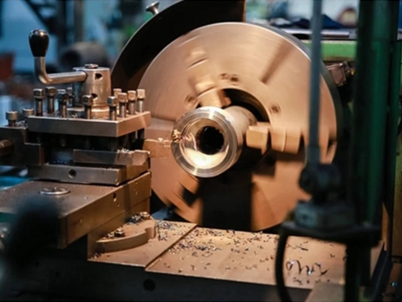
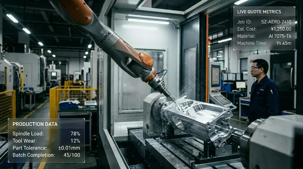
Medical CNC machining is not one process. Turning favors rotational parts and can establish critical coaxial relationships. Milling handles prismatic forms, pockets, flats, and complex external profiles. Grinding may be needed where surface condition, roundness, or diameter control is central to function. Centerless grinding suits certain small cylindrical forms but requires a part geometry that can be supported and controlled through the process.
EDM can address difficult internal or fine features without conventional cutting forces, while laser processing can be useful for certain small-feature applications. Each option leaves its own questions about affected surfaces, edge quality, accessibility, and inspection. Buyers should resist specifying a process prematurely unless the process itself is a validated design constraint. State the required function and feature condition first; then require the supplier to explain the proposed method and its known limits.
Sanluo Precision lists turning, milling, micro machining, laser beam machining, EDM, and several grinding methods among its medical CNC machining capabilities. That range matters most where a component has competing risks—for example, a small turned body with a delicate cross-hole and a surface that needs final refinement. A single process may not be the best answer.
Grouping all medical parts under “high precision” leads to bad purchasing decisions. The function of the device should drive the feasibility review.
Components for minimally invasive instruments commonly combine narrow working envelopes with long shafts, moving interfaces, and small functional details. A surface that drags, a sharp edge that catches, or a hole that is slightly misplaced can change actuation feel or interfere with assembly. Surface requirements therefore need context. “Smooth” is not a usable machining instruction; identify the contact condition, direction of motion, cleaning concern, and acceptance method.
Ask how the supplier will maintain feature relationships after multiple setups and how burrs will be managed at intersections. Those are practical questions, not paperwork.
Medical implant component machining often places the emphasis on threads, mating geometries, contoured forms, and surface condition. For medical bone screw machining, thread form is only part of the review; the relationship between the drive feature, shank, thread, and any associated interface deserves equal attention. Dental pins may bring small-diameter handling and concentricity concerns. High-precision diagnostic components can introduce optical, fluidic, or sensor-interface requirements that make tiny passages and surface defects consequential.
Sanluo Precision describes work involving artificial joints, spinal fixation parts, bone screws, dental pins, minimally invasive instruments, and diagnostic equipment. That breadth should not replace a part-specific review. It is a reason to ask informed questions early, especially for medical micro machining work involving thin walls, micro-diameter rods, or tiny holes.
Inspection should be planned with the process, not added after the first article arrives. Critical dimensions need defined datums, a measurement method suited to the feature, and a clear record of what will be reported. Surface verification deserves the same discipline. Visual inspection alone may not answer whether a surface supports the intended motion, fit, or cleanliness requirement.
There is also no substitute for an engineering review with a person who can challenge the drawing. Useful questions include: Can this feature be reached with the proposed tool? What happens to the part after it leaves the fixture? Which feature must be made first to preserve the datum scheme? Is a requested tolerance necessary for function, or has it been carried over from an early concept?
A supplier that only accepts the file and promises compliance has not reduced much risk. You want comments on manufacturability, inspection access, sequence, and areas where the design leaves room for interpretation.