
The smallest advertised diameter rarely tells you whether a supplier can make your part reliably. A hole can be technically drillable yet fail because of position error, entry breakout, taper, trapped chips, tool marks, or an unacceptable burr on a surface you can’t reach afterward.
Start by identifying the failure that would make the part unusable. For an orifice, diameter consistency and surface condition may control flow. In a medical or semiconductor component, residual debris may be the larger concern. A cooling passage may depend on intersection location, while an angled vent can fail if the drill walks across the entry surface. Effective micro hole drilling services should evaluate that functional risk before proposing a tool or quoting a tolerance.
A useful classification has four criteria: hole depth relative to diameter, access at the entrance and exit, entry angle, and the relationship between one hole and the next. These factors determine how the tool is guided, how chips and coolant leave the cut, and how the finished feature can be inspected.
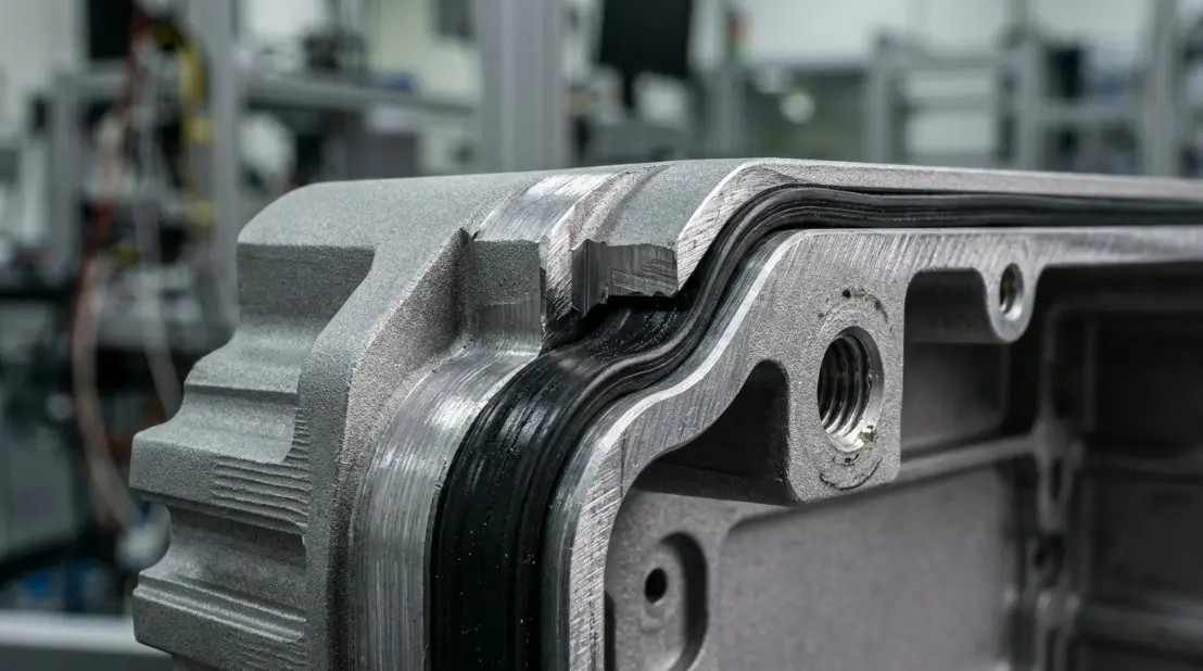
A through hole provides an exit, but breakthrough can produce a burr or edge damage on the far side. That surface may be buried inside a component or too delicate for conventional deburring. Exit condition therefore belongs on the drawing, not in an assumption made after parts arrive.
A blind hole has no chip exit. Chips must travel back along the tool flutes, and the specified depth must distinguish usable cylindrical depth from the drill-point region. Inspection is also harder: an entrance view doesn’t prove bottom geometry, full depth, or internal surface condition.
As depth-to-diameter ratio rises, tool deflection, chip packing, heat, and breakage become more influential. Angled entry makes the cutting edges engage unevenly, increasing the chance of walking or entry damage. A prepared spot, supporting geometry, or a different process may be needed.
Intersecting holes introduce breakthrough risks inside the part and may leave burrs where passages meet. Arrayed holes shift the problem toward repeat positioning, tool wear, and consistency across the pattern. One acceptable hole doesn’t establish that an entire array will meet position and diameter requirements.
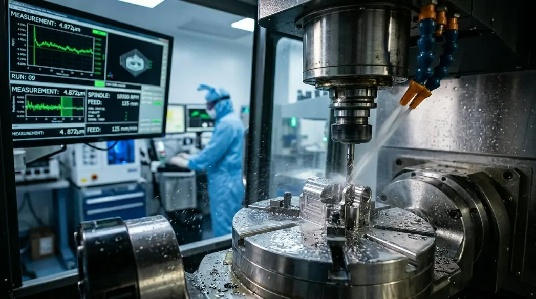
Mechanical micro drilling removes material through direct cutting. Depending on the geometry, the process may use straight-fluted drills, twist drills, or gun drills. Tool family, edge geometry, spindle behavior, workholding, and chip-removal strategy must be selected together; simply fitting a smaller drill into a conventional setup isn’t enough.
For many metals, mechanical drilling is a practical choice when the drawing calls for a defined cylindrical hole and the material can be cut without excessive tool wear or work hardening. Stainless steel and titanium deserve particular attention to heat, chip formation, and tool condition. Brittle materials can chip at entry or exit, while engineering plastics can smear, soften, or recover dimensionally after cutting.
The process is most attractive when physical access is available, cutting forces can be tolerated, and the required burr condition is achievable by tool control or an approved secondary operation. Sanluo Precision’s precision micro drilling capabilities cover standard, deep, blind, through, angled, intersecting, and arrayed-hole geometries, but each still requires a feature-level review.
Process comparisons should use the same drawing, material, quantity, and acceptance criteria. Otherwise, buyers end up comparing a drilled production hole with an EDM feasibility claim or a laser cycle-time estimate that excludes recast removal and inspection.
| Requirement | Mechanical drilling | Micro EDM | Laser drilling |
|---|---|---|---|
| Material compatibility | Metals, selected brittle materials, and engineering plastics; machinability affects tool life and edge quality | Requires an electrically conductive workpiece | Applicable to many materials, subject to absorption and thermal response |
| Deep or blind geometry | Possible with suitable tooling and chip evacuation; risk rises with depth-to-diameter ratio | Useful for difficult conductive materials and small features, with electrode wear and flushing considered | Depth, taper, and debris removal can limit suitability |
| Angled entry | Tool walking and uneven engagement require careful support | Avoids conventional cutting force but still needs stable positioning and access | Beam access is favorable, though focus and entry shape must be controlled |
| Typical edge concern | Mechanical burrs, breakout, or chipping | Recast layer and electrode-related variation | Heat-affected material, recast, taper, and spatter |
| Production consideration | Tool wear and breakage must be controlled across the lot | Cycle time, electrode behavior, and dielectric flushing matter | Fast material removal may suit arrays, provided thermal effects meet the drawing |
Micro drilling versus EDM drilling is not a simple speed contest. EDM can solve features in hard conductive materials without conventional cutting forces, but it isn’t available for nonconductive plastics or ceramics. Laser drilling avoids physical tool contact, yet a fast hole with unacceptable taper or thermal damage is not a finished feature.
“Micron-level hole” is not a complete specification. Diameter tolerance, position tolerance, depth, angle, surface roughness, and burr acceptance describe different risks and may require different controls. Tightening all of them by default raises micro hole drilling cost and can eliminate otherwise suitable processes.
State where each requirement applies. A diameter measured only at the entrance doesn’t define taper. A general deburr note may not cover an inaccessible intersection. If surface condition affects flow, sealing, fatigue, cleanliness, or assembly, name the relevant area and the evidence required to accept it.
A defensible request for quote includes the material grade and condition, finished hole diameter, depth or through condition, entry angle, location relative to datums, number of holes per part, and order quantity. Identify any coatings, heat treatment, or secondary operations that occur before or after drilling.
Also separate must-have requirements from preferences. If the exit face is hidden in service, say whether an exit burr is prohibited, limited, or removable by an approved secondary process. For low-volume orders, clarify whether sectioned first articles or process-development samples are acceptable.
Inspection must be able to see the characteristic it is supposed to verify. Optical microscopy can document accessible entries, exits, and visible burrs. Dimensional inspection can establish position and repeat positioning when the feature and datum scheme are measurable. Hidden intersections, internal taper, blind-hole bottoms, and subsurface condition may require sectioning or another agreed method.
Destructive inspection changes cost and sample planning. Decide before production whether sectioned parts come from setup samples, first articles, or the production lot, and define what happens if a hidden feature fails.
-