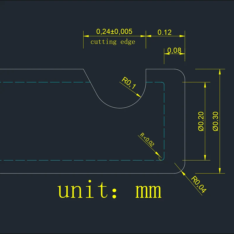
When drawings call out diameter tolerances inside the micrometer band, the question is no longer whether a shop can cut metal, but whether it can prove every dimension on every piece. Precision machining with strict dimensional tolerance control is the discipline that links machine positioning stability, process planning, gauge selection and final verification into one closed loop. Sanluo Precision has run this loop for over 18 years from its Shenzhen facility, serving medical, semiconductor and optical communication customers and directly or indirectly supporting Bosch, ZF and NSK supply chains. The sections below walk through where control begins, what IT grades are held, how dimensions are verified, where fit tolerance decides function, and what separates a capable dimensional-control shop from a general CNC workshop.
Dimensional tolerance control does not begin at the first cut; it begins with the machine itself. A machining center whose axes cannot repeat to a micron cannot produce parts whose diameter is held to IT1, regardless of operator skill. At Sanluo Precision the workstation is specified so that linear positioning on the Z axis reaches ±0.0001/mm, on the Y axis ±0.0005/mm and on the X axis ±0.001/mm, with geometric flatness of ±0.0003/mm already built into the granite and drive layout. This is the ceiling against which every process plan is written.
Thermal stability is the second pillar. Spindle heat, ambient drift and coolant temperature all expand the workpiece and the machine frame by amounts that dwarf a 0.001mm tolerance. The shop therefore runs temperature-controlled cutting strategies, lets spindles warm up before metrology-critical operations, and sequences roughing, semi-finishing and finishing so that residual stress and heat input do not compromise the final pass. Precision machining with strict dimensional tolerance control treats the first few microns of allowance as a separate process step rather than an afterthought.
Process planning closes the loop. Before a cutter touches the blank, the process engineer maps which dimensions are IT-grade, which are fit-critical (shaft h2/h3 against hole H2/H3), and which geometric calls (roundness, concentricity, runout) must survive after grinding or boring. Each call is routed to the operation that can hold it: cylindrical grinding for roundness, jig boring for hole position within ±0.002mm, precision boring for bores from φ10 to 500mm. The inspection plan is written at the same time as the process plan, so that every tolerance on the drawing has a defined gauge and a defined operator.
The table below is the capability statement that Sanluo Precision uses when quoting a new part. It consolidates the IT grades the plant commits to, the dimensional and geometric accuracy of the workstation, the machining methods available, and the inspection instruments that back them up. Procurement engineers can read it directly against their own drawing callouts.
Sanluo Precision's tight tolerance machining implements strict tolerance control: Dimensional tolerance (diameter IT0 grade ±0.0002mm-IT1 grade ±0.001mm, length tolerance ±0.002-0.015mm); fit tolerance (shaft h2/h3 grade, hole H2/H3 grade, tolerance zone ±0.002-0.008mm); geometric tolerance (roundness 0.0005-0.005mm, flatness 0.0005-0.015mm, perpendicularity 0.001-0.02mm, concentricity 0.002-0.015mm, runout 0.002-0.03mm, position tolerance 0.002-0.05mm); surface roughness Ra0.05-1.6μm.
|
dimensional accuracy |
L(X) |
W(Y) |
H(Z) |
SW |
GD |
|
unit:±/mm |
0.001 |
0.0005 |
0.0001 |
0.002 |
0.001 |
|
Geometric accuracy |
flatness |
parallelism |
perpendicularity |
symmetry |
Position tolerance |
|
unit:±/mm |
0.0003 |
0.001 |
0.001 |
0.002 |
0.002 |
|
production capacity |
1~999999 pcs |
1~999999 pcs |
1~999999 pcs |
1~999999 pcs |
1~999999 pcs |
|
production cycle |
3-20 days |
3-20 days |
3-20 days |
3-20 days |
3-20 days |
Sanluo Precision's processing plant adopts a variety of machining technologies for tight tolerance machining: precision turning (diameter φ0.05-500mm, tolerance IT6 grade ±0.003-0.006mm, roundness 0.003mm), precision milling (flat tolerance ±0.002mm, hole position tolerance ±0.015mm), precision grinding (cylindrical grinding/internal grinding/surface grinding, tolerance IT5 grade ±0.001mm, roundness 0.001mm), precision boring (aperture φ10-500mm, tolerance IT5 grade ±0.002-0.01mm), precision drilling (diameter φ0.1-50mm, position tolerance ±0.02mm), jig boring (hole position accuracy ±0.002mm, for precision molds/fixtures).
As a professional manufacturer of tight tolerance machining, Sanluo Precision implements strict inspection assurance: dimensional inspection (CMM measuring accuracy 0.002mm for measuring dimensional tolerance/hole distance tolerance; laser instrument/ultra-precision micrometer/micrometer/vernier caliper/plug gauge/ring gauge/thread gauge for detecting diameter/length tolerance); Application cases: precision molds (cavity dimensional tolerance ±0.01mm, stamping die gap tolerance ±0.005mm), precision fixtures (locating pin hole H7 grade ±0.005mm, positioning accuracy ±0.01mm), measuring instruments (micrometer anvil flatness 0.003mm, plug gauge tolerance ±0.002mm), precision transmission (gear tooth profile IT6 grade, bearing inner and outer rings IT5 grade ±0.002mm), hydraulic and pneumatic (cylinder bore H7 grade ±0.006mm, spool fit tolerance ±0.003mm). We have directly or indirectly provided customized high precision machining services to Bosch, ZF, NSK and other enterprises, with an annual output of 200,000 pieces and a qualification rate of 99.8%.
|
Parameter Category |
Parameter Details |
|
Equipment Model |
JDSGT400 Linear Motor Driven 3-axis High-Speed Machining Center |
|
Core Positioning |
For submicron-level ultra-high precision machining |
|
Drive System |
All three axes adopt dual linear motor drive |
|
Key Accuracy |
Repeat positioning accuracy up to 0.8 microns; hole position accuracy less than 1 micron within 100 mm range. |
|
Core Technology |
Integrates direct drive, temperature control, self-developed JD60 CNC system precision machining features and high-precision servo drive system |
|
Core Advantage |
Committed to achieving the excellent effect of "surface is the functional surface" |
|
Typical Application |
tight tolerance machining of precision optical molds, semiconductor parts, high-precision structural parts and other products with strict requirements on dimensions and surface quality |
|
Parameter Category |
Parameter Details |
|
Equipment Model |
Micro5 Micron-level High-precision 5-axis Machining Center |
|
Core Positioning |
High dynamic performance and high-precision machining of miniature, high value-added parts |
|
Key Accuracy |
Repeat positioning accuracy 0.0005mm, positioning accuracy < 0.002mm |
|
Spindle System |
Maximum spindle speed 60,000 rpm |
|
Structural Features |
Compact structure with total weight 550kg; equipped with three-layer tool magazine with capacity of 60 tools; processing area pallet system can hold 6 zero-point fixtures |
|
Energy Saving and Environmental Protection |
Extremely low energy consumption (<500W), equipped with oil mist collector |
|
CNC System |
German Beckhoff system |
|
Stroke (X/Y/Z) |
78 / 56 / 50 mm |
|
Typical Application |
tight tolerance machining of miniature engineering components, small precious metal parts, etc. |
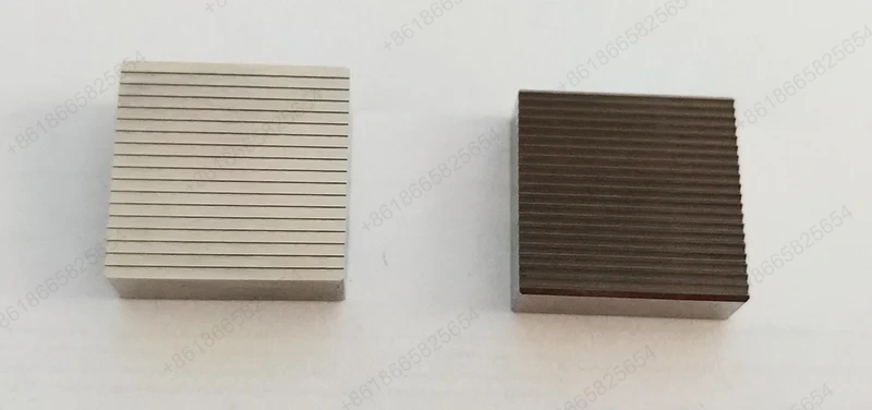
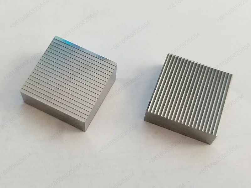
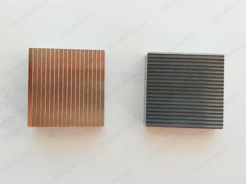
Read together, these tables define what precision machining with strict dimensional tolerance control commits to on a real drawing: the IT grade on the diameter, the IT grade on the bore, the geometric call on the critical face, and the gauge that signs off the result.
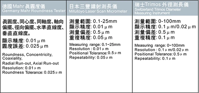
A tolerance that is not measured is a tolerance that is not controlled. The inspection chain at Sanluo Precision is arranged so that each class of dimension on the drawing has a named instrument with a known measurement uncertainty. The three layers of verification are:
1. CMM inspection: a three-coordinate measuring machine with measuring accuracy of 0.002mm is used for overall dimensional verification and hole-distance tolerance, recording positions, parallelisms and true positions in a report that accompanies the batch.
2. Precision comparative metrology: laser instruments and ultra-precision micrometers are used for diameter and length trending between CMM cycles, catching drift before it reaches the tolerance boundary; ordinary micrometers and vernier calipers handle the non-critical diameters that still need to be inside the band.
3. Go/no-go and thread gauging: plug gauges, ring gauges and thread gauges sign off fit-critical diameters and threaded features directly against the drawing's shaft h2/h3 and hole H2/H3 requirements, so that fit is proven by gauge rather than inferred from a single micrometer reading.
Together these instruments turn a machined part into a documented part, which is what dimensional control on a production order actually means. For engineering teams used to receiving only a signed-off part, the shift to a report-driven workflow is the practical difference that precision machining with strict dimensional tolerance control is designed to deliver.
Fit tolerance is not a cosmetic number. It decides whether a shaft turns freely, whether a locating pin repeats its position, and whether a cylinder bore seals. The plant's documented application cases show where a ±0.003mm swing changes the function of the component:
• Precision molds: cavity dimensional tolerance held at ±0.01mm, stamping die gap tolerance at ±0.005mm, so that the gap between punches and dies controls burr height on the stamped part.
• Precision fixtures: locating pin holes at H7 grade ±0.005mm with overall positioning accuracy ±0.01mm, which is the difference between a fixture that repeats and one that accumulates error over a shift.
• Measuring instruments: micrometer anvil flatness at 0.003mm and plug gauge tolerance at ±0.002mm, where the part itself is the gauge and any geometric error propagates into every downstream measurement.
• Precision transmission: gear tooth profile at IT6 grade, bearing inner and outer rings at IT5 grade ±0.002mm, controlling backlash, noise and bearing life in rotating assemblies.
• Hydraulic and pneumatic: cylinder bore at H7 grade ±0.006mm and spool fit tolerance ±0.003mm, where leakage and hysteresis are direct functions of the clearance between spool and bore.
Across these five families the same principle applies: the fit tolerance on the drawing is translated into a process route, a gauge and an inspection report before production begins.
Procurement engineers evaluating a dimensional-control shop usually ask three questions before releasing a drawing:
1. Industrial track record: has the shop held these tolerances at production volume? Sanluo Precision has directly or indirectly supplied Bosch, ZF and NSK through tiered supply chains, and runs an annual output of roughly 200,000 pieces with a 99.8% qualification rate, which is the volume and stability evidence that a single prototype cannot provide.
2. Independent quality system: is inspection separated from machining? The plant fields 16 quality management staff across QE, IQC, IPQC and OQC, with 320+ pieces of testing equipment including CMMs, image analyzers, tool microscopes, projectors, height gauges and roughness testers, so that in-process and outgoing checks are not signed by the operator who made the part.
3. Documented evidence flow: does the customer receive the data? Inspection reports are issued with each batch, covering the dimensions called out on the drawing, the instrument used, and the measured value; drawings can be treated under customer confidentiality agreements and the production workshop access policy follows the same rule.
A supplier that can answer all three with verifiable evidence is operating at the level that precision machining with strict dimensional tolerance control demands, rather than at the level of a prototype shop.
Dimensional control does not stop when the part leaves the machine. A shaft ground to ±0.001mm and then rattled against a mating part in a cardboard box arrives with burrs, bruises and corrosion marks that no inspection report can undo. Shipping protection is therefore part of the tolerance loop, not a separate logistics concern.
Parts are classified before packing. Critical mating surfaces, ground bores, polished cavities and locating pins are wrapped individually in anti-corrosion film or foam, and separated from one another so that metal-to-metal contact is impossible in transit. Sharps, thin walls and cantilevered features are supported rather than hung, because flexure during shipping is the same physical error as flexure during machining. The outer carton is chosen to survive normal handling: per the plant's internal standard the box withstands one hour of water immersion and survives a 1-meter free drop without damaging the parts inside, and customer-specified packaging standards are followed wherever the drawing or purchase order defines them.
Documentation travels with the parts. Inspection reports, material certificates and any first-article records are packed in a waterproof envelope inside the box so that the receiving engineer can match delivered serial numbers to measured dimensions on the bench. For international shipments the plant coordinates with forwarders experienced in precision components, and consolidates smaller runs to reduce handling cycles. The objective is simple: the part that the customer measures on arrival is the same part that left the CMM. Shipping protection is therefore treated as a continuation of precision machining with strict dimensional tolerance control, not as a separate logistics task.
The closed loop described above — machine positioning, process planning, gauge selection, documented inspection and protective delivery — is what separates dimensional tolerance control from ordinary CNC production. The IT0 to IT1 diameter band, the H2/H3 fit zone, the CMM at 0.002mm and the 99.8% qualification rate are not marketing labels; they are checkpoints on the route from a first drawing to a repeatable production batch.
A: IT grades describe the tolerance band in micrometers for a given nominal diameter. A lower number means a tighter band. Sanluo Precision works in the IT0 to IT1 band on diameters (±0.0002mm to ±0.001mm) and IT5 to IT6 on features routed through grinding, boring or precision turning. When you compare suppliers, ask which IT grade they commit to on your exact nominal size rather than on a sample diameter, because the same IT grade allows a wider band as the nominal grows.
A: Yes, and most production drawings do. A shaft may carry IT1 on a bearing journal, IT5 on a locating diameter and IT8 on a thread runout. The process plan routes each feature to the operation that can hold that grade: cylindrical or internal grinding for IT5 and tighter, jig boring for hole position inside ±0.002mm, precision turning for IT6 features on rotational parts. The drawing should mark each critical feature clearly, because the cost and lead time scale with the sum of the tightest calls, not with the average.
A: The report is built around three layers. The CMM (measuring accuracy 0.002mm) records overall dimensions, hole positions and geometric calls; laser instruments and ultra-precision micrometers trend diameter and length between CMM cycles; plug, ring and thread gauges sign off fit-critical features against H2/H3 and h2/h3 requirements. Each measured value on the report is tied to the instrument used, so your quality team can verify measurement uncertainty on the features that matter most.
A: A dimensioned 2D drawing in PDF or STEP format, with material specified (or a preferred equivalent), heat-treatment state, critical tolerances circled or flagged, surface roughness callouts and any threaded or fit-critical features marked. Indicate whether first-article inspection reports are required and whether material certificates need to accompany the batch. Quotations are normally returned within 0–2 working days once the drawing is complete; if design options are needed, the engineering group typically delivers them within 1–3 weeks.
A: The plant accepts an MOQ of one piece, so a single prototype or a short first-off batch can be launched on the same drawing as the eventual production run. Sample fees apply for first-off tooling and metrology work. This is useful when a new tolerance call has not yet been proven on a supplier: run a one- or two-piece trial, review the inspection report, and only then release the production batch.
A: Non-conforming parts are segregated at the OQC station and the quality engineer opens a deviation record tied to the serial numbers and the measured dimensions. Options include rework within the existing process capability, concession review against the customer's tolerance, or replacement production at the plant's cost when the deviation is confirmed to originate in the machining process. The 99.8% qualification rate is tracked from this record, so trends on a given feature or material are visible before they become a recurring issue.