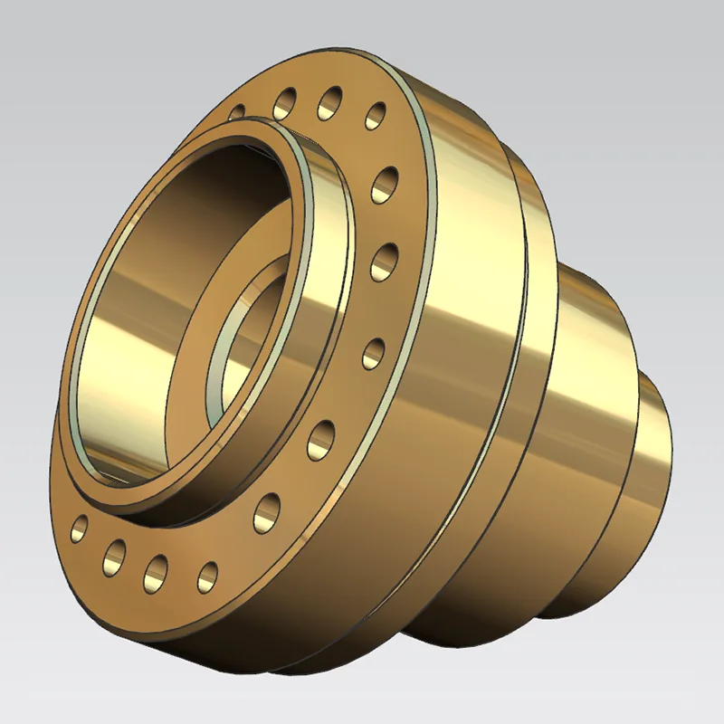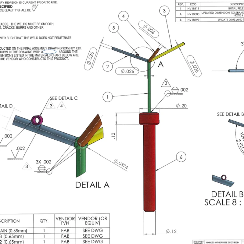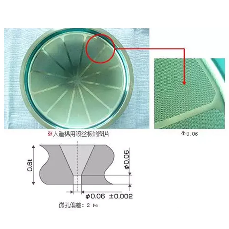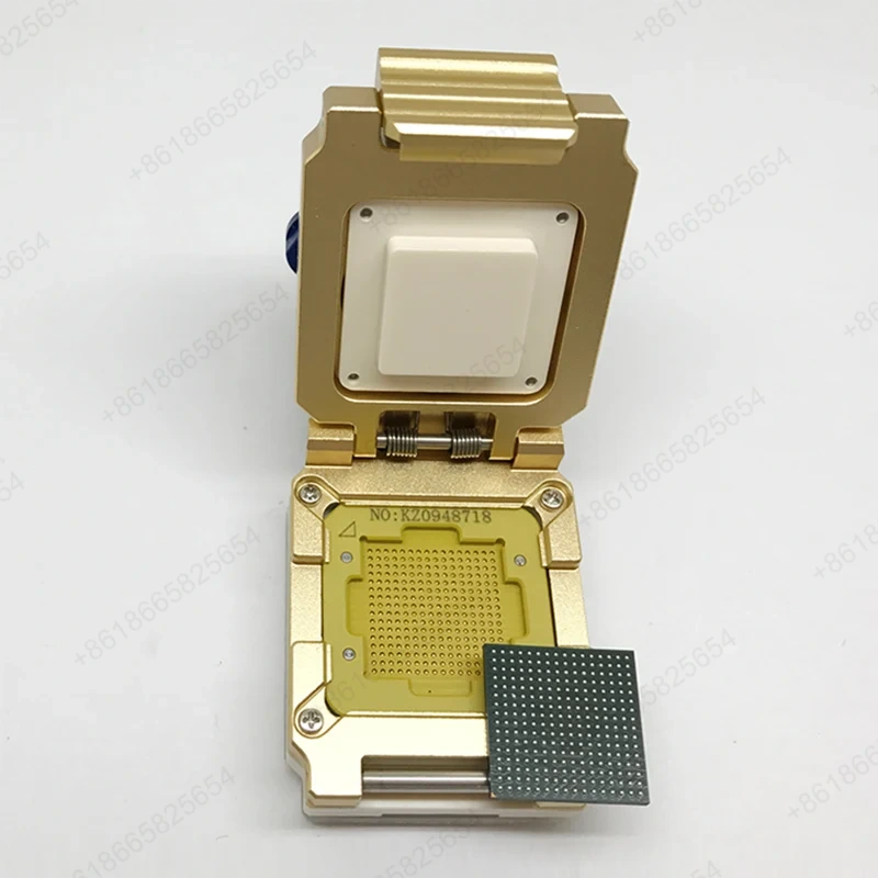
An optical mold cavity does two jobs at once: it defines the geometry of every lens, prism or light-guide it presses, and it transfers its own surface finish onto the plastic. That is why tight tolerance machining for optical mold components is judged on a double constraint — dimensional tolerance and surface quality treated as one functional system. Sanluo Precision has equipped its Shenzhen plant with submicron-class centers and pairs them with in-process and post-process metrology so that cavity tolerance, gate geometry and parting-line flatness arrive documented on the inspection report. The sections below explain why mold work sets the highest bar, which machines are configured for it, what cavity tolerance data the work demands, how surface finish is treated as a functional requirement, how material and process planning are arranged, and how samples, lead time and after-sales support are handled.
In most mechanical parts, a 5µm error on a non-mating face is invisible. In an optical mold, the same 5µm on a cavity curve translates directly into optical power error, astigmatism or wave-front distortion on every lens produced from that cavity. The cavity is not a housing; it is the master surface that the molded part copies, so its tolerance band is set by optical tolerancing, not by general mechanical tolerancing. This is the first reason the bar is high.
The second reason is surface. Plastic replication does not hide a poor cavity finish; it amplifies it. A tool that leaves tool marks, orange peel or subsurface stress will reproduce those features on the lens, and polishing after molding adds cost, cycle time and another uncontrolled variable. The mold maker therefore asks the machining shop to reach the required surface directly — what Sanluo Precision describes as the principle that "surface is the functional surface" — so that the cavity arrives ready for inspection rather than ready for rework.
The chain runs from machine positioning to cavity geometry to plastic shrinkage to the final lens. A cavity held at ±0.01mm on dimensional tolerance, with roundness and concentricity controlled at the sub-0.005mm level, leaves the mold maker room to compensate for shrinkage in the design. A cavity whose geometry drifts between cavities forces the mold maker to re-tune each tool individually, which is the situation that tight tolerance machining for optical mold components is designed to prevent.
Mold-class finishing asks the machine to hold position through long, fine-finishing cuts at high spindle speed, with thermal drift minimized across hours rather than minutes. The plant fields two configurations matched to different scales of mold work:
1. JDSGT400 linear-motor 3-axis high-speed machining center: all three axes use dual linear motor drive, giving repeat positioning accuracy up to 0.8µm and hole position accuracy below 1µm within a 100mm range. The machine integrates direct drive, temperature control, the self-developed JD60 CNC system and a high-precision servo drive, and is positioned for submicron-level ultra-high precision work on precision optical molds, semiconductor parts and high-precision structural parts.
2. Micro5 micron-level 5-axis machining center: repeat positioning accuracy of 0.0005mm with positioning accuracy under 0.002mm, a maximum spindle speed of 60,000 rpm, a 60-tool magazine and a pallet system that holds 6 zero-point fixtures. It uses a German Beckhoff CNC system, has X/Y/Z strokes of 78/56/50mm, weighs 550kg, and consumes under 500W with an oil mist collector — a configuration suited to miniature mold inserts, small optical inserts and high-value miniature components where fixturing repeatability matters as much as spindle accuracy.
3. Supporting precision operations: cylindrical, internal and surface grinding at IT5 ±0.001mm with roundness 0.001mm, jig boring at hole position ±0.002mm, and precision boring for bores from φ10 to 500mm complete the route when mold bases, guide pillars, sleeves and related steel ancillaries need to be finished alongside the cavity.
Together these machines cover the range from large mold-base finishing to sub-millimeter optical inserts, without forcing the mold maker to split the job across multiple suppliers. This is the equipment baseline that tight tolerance machining for optical mold components is built on.
The table below is the capability statement Sanluo Precision publishes for mold-class work. It consolidates the IT grades the plant commits to, the workstation dimensional and geometric accuracy, the machining methods available, and the inspection instruments that back them up. Optical mold makers can read it directly against their cavity, insert and mold-base drawings.
Sanluo Precision's tight tolerance machining implements strict tolerance control: Dimensional tolerance (diameter IT0 grade ±0.0002mm-IT1 grade ±0.001mm, length tolerance ±0.002-0.015mm); fit tolerance (shaft h2/h3 grade, hole H2/H3 grade, tolerance zone ±0.002-0.008mm); geometric tolerance (roundness 0.0005-0.005mm, flatness 0.0005-0.015mm, perpendicularity 0.001-0.02mm, concentricity 0.002-0.015mm, runout 0.002-0.03mm, position tolerance 0.002-0.05mm); surface roughness Ra0.05-1.6μm.
|
dimensional accuracy |
L(X) |
W(Y) |
H(Z) |
SW |
GD |
|
unit:±/mm |
0.001 |
0.0005 |
0.0001 |
0.002 |
0.001 |
|
Geometric accuracy |
flatness |
parallelism |
perpendicularity |
symmetry |
Position tolerance |
|
unit:±/mm |
0.0003 |
0.001 |
0.001 |
0.002 |
0.002 |
|
production capacity |
1~999999 pcs |
1~999999 pcs |
1~999999 pcs |
1~999999 pcs |
1~999999 pcs |
|
production cycle |
3-20 days |
3-20 days |
3-20 days |
3-20 days |
3-20 days |
Sanluo Precision's processing plant adopts a variety of machining technologies for tight tolerance machining: precision turning (diameter φ0.05-500mm, tolerance IT6 grade ±0.003-0.006mm, roundness 0.003mm), precision milling (flat tolerance ±0.002mm, hole position tolerance ±0.015mm), precision grinding (cylindrical grinding/internal grinding/surface grinding, tolerance IT5 grade ±0.001mm, roundness 0.001mm), precision boring (aperture φ10-500mm, tolerance IT5 grade ±0.002-0.01mm), precision drilling (diameter φ0.1-50mm, position tolerance ±0.02mm), jig boring (hole position accuracy ±0.002mm, for precision molds/fixtures).
As a professional manufacturer of tight tolerance machining, Sanluo Precision implements strict inspection assurance: dimensional inspection (CMM measuring accuracy 0.002mm for measuring dimensional tolerance/hole distance tolerance; laser instrument/ultra-precision micrometer/micrometer/vernier caliper/plug gauge/ring gauge/thread gauge for detecting diameter/length tolerance); Application cases: precision molds (cavity dimensional tolerance ±0.01mm, stamping die gap tolerance ±0.005mm), precision fixtures (locating pin hole H7 grade ±0.005mm, positioning accuracy ±0.01mm), measuring instruments (micrometer anvil flatness 0.003mm, plug gauge tolerance ±0.002mm), precision transmission (gear tooth profile IT6 grade, bearing inner and outer rings IT5 grade ±0.002mm), hydraulic and pneumatic (cylinder bore H7 grade ±0.006mm, spool fit tolerance ±0.003mm). We have directly or indirectly provided customized high precision machining services to Bosch, ZF, NSK and other enterprises, with an annual output of 200,000 pieces and a qualification rate of 99.8%.
|
Parameter Category |
Parameter Details |
|
Equipment Model |
JDSGT400 Linear Motor Driven 3-axis High-Speed Machining Center |
|
Core Positioning |
For submicron-level ultra-high precision machining |
|
Drive System |
All three axes adopt dual linear motor drive |
|
Key Accuracy |
Repeat positioning accuracy up to 0.8 microns; hole position accuracy less than 1 micron within 100 mm range. |
|
Core Technology |
Integrates direct drive, temperature control, self-developed JD60 CNC system precision machining features and high-precision servo drive system |
|
Core Advantage |
Committed to achieving the excellent effect of "surface is the functional surface" |
|
Typical Application |
tight tolerance machining of precision optical molds, semiconductor parts, high-precision structural parts and other products with strict requirements on dimensions and surface quality |
|
Parameter Category |
Parameter Details |
|
Equipment Model |
Micro5 Micron-level High-precision 5-axis Machining Center |
|
Core Positioning |
High dynamic performance and high-precision machining of miniature, high value-added parts |
|
Key Accuracy |
Repeat positioning accuracy 0.0005mm, positioning accuracy < 0.002mm |
|
Spindle System |
Maximum spindle speed 60,000 rpm |
|
Structural Features |
Compact structure with total weight 550kg; equipped with three-layer tool magazine with capacity of 60 tools; processing area pallet system can hold 6 zero-point fixtures |
|
Energy Saving and Environmental Protection |
Extremely low energy consumption (<500W), equipped with oil mist collector |
|
CNC System |
German Beckhoff system |
|
Stroke (X/Y/Z) |
78 / 56 / 50 mm |
|
Typical Application |
tight tolerance machining of miniature engineering components, small precious metal parts, etc. |


Read against a cavity drawing, this is the data set that matters: cavity dimensional tolerance around ±0.01mm, stamping die gap at ±0.005mm on related steelwork, geometric flatness down to 0.0005mm on critical faces, and CMM verification at 0.002mm on every delivered insert.
Surface finish on an optical cavity is not a cosmetic callout. It is the specification that decides whether the molded lens needs secondary polishing, whether a light-guide will scatter, and whether a screen lens will show tool marks through the plastic. The plant treats roughness as a functional requirement in the same category as tolerance:
• Achievable roughness band: surface roughness holds Ra0.05–1.6µm across the machined surface, with the lower end reached on fine-finishing passes routed through the linear-motor center and the high-speed spindle.
• "Surface is the functional surface": this is the working principle on the JDSGT400, meaning the final machined surface is intended to be the surface that meets the plastic, not a pre-polish stage that is later hand-finished. It reduces the number of uncontrolled steps between steel and optical part.
• Fit and geometric requirements alongside roughness: flatness of 0.0005–0.015mm, concentricity of 0.002–0.015mm and runout of 0.002–0.03mm are held on the same faces where the roughness call is tightest, because a mirror surface on a tilted face still produces a defective lens.
• Measurement: roughness testers sit alongside the CMM and the microscope stations, so that the surface report on the inspection sheet is measured rather than assumed from the tool path.
For mold makers, the practical implication is that the cavity arrives with both a dimensional report and a roughness report on the same feature, rather than one being measured and the other estimated. This combined report is the deliverable that makes tight tolerance machining for optical mold components auditable on the customer's own bench.
Material choice sets the boundary of what the machine can achieve. The plant works across the common mold-steel and insert-material families and routes each one through a process plan matched to its hardness, toughness and grinding behavior:
1. Mold steel and pre-hardened grades: routed through milling and finishing on the linear-motor center, with allowance left for post-hardening grinding when the drawing calls for hardness after rough machining. The process plan separates roughing (where stock removal dominates), semi-finishing (where stress is relieved) and finishing (where tolerance and roughness are reached).
2. Hardened and high-wear insert materials: routed through precision grinding — cylindrical, internal or surface — at IT5 ±0.001mm with roundness 0.001mm, which is the operation that can still hold tolerance after the steel is hardened. Jig boring at hole position ±0.002mm is used for insert locating holes that must repeat between cavities.
3. Supporting processes integrated from the surrounding supply chain: vacuum heat treatment, surface coatings, ion polishing, electrolytic polishing, fluid polishing and other secondary operations are coordinated with the machining steps, so that the cavity leaves the plant with the full process chain documented rather than split across uncoordinated subcontractors.
The objective of this planning is to keep the tolerance and the roughness call stable across the whole route, rather than trading one against the other at each operation.
Mold work usually begins with a single cavity, a single insert or a trial mold component rather than a full production order. The plant accepts a minimum order of one piece, so that a first-off cavity can be cut, inspected and shipped before any commitment to a full tool. Sample fees apply for first-off work, and quotation is normally returned within 0–2 working days once the drawing is complete; where design options or process review are needed, the engineering group typically delivers them within 1–3 weeks.
Production lead time for the machining step itself is 3–20 days depending on part size, number of operations and inspection density, measured from the release of the production drawing. The plant runs an annual output of roughly 200,000 pieces with a 99.8% qualification rate, so once a cavity design is proven, repeat orders on related inserts or mold-base components fit into the same production slots rather than restarting the process plan each time.
After delivery, engineering support continues through the quality group: the same QE, IQC, IPQC and OQC structure that signed off the first-off part remains responsible for later batches, and inspection reports are reissued on request when the customer's own metrology flags a drift. If a non-conforming insert is identified on the customer's bench, the plant treats it as a deviation record tied to serial numbers, measured values and the machining route, and coordinates rework or replacement based on the recorded data rather than anecdotal feedback.
For optical mold makers, the combined picture is straightforward: a submicron-class machine configuration, a documented cavity tolerance band, a roughness call that is treated as functional, a material-aware process plan, and a sample-to-production route that keeps the same engineering team on the drawing from first-off to repeat order. That is the basis on which tight tolerance machining for optical mold components is delivered as a controlled process rather than as a one-off machining service.
A: The plant works across the common mold-steel and insert families used in optical injection tooling, including pre-hardened mold steels, hardened wear-resistant steels and powder high-speed steel grades for high-cycle inserts, as well as stainless steels for corrosion-sensitive optical applications. Material choice is confirmed against the drawing's hardness and wear requirements before quoting; if you have a specific steel grade in mind, send it with the drawing and the process plan will be built around its machinability and grinding behavior.
A: The achievable roughness band is Ra0.05–1.6µm. The lower end of the band is reached on fine-finishing passes routed through the linear-motor center at high spindle speed; the upper end applies to non-optical faces such as mold-base surfaces and ancillary steelwork. Roughness is measured on the delivered part with roughness testers and reported on the inspection sheet alongside the dimensional report, so the optical face is documented rather than visually assessed.
A: Documented application cases run at cavity dimensional tolerance around ±0.01mm and stamping die gap tolerance at ±0.005mm on related steelwork, with geometric calls on critical faces in the 0.0005–0.015mm flatness band. Diameter capability reaches IT0 at ±0.0002mm to IT1 at ±0.001mm, and fit zones on shaft h2/h3 against hole H2/H3 sit at ±0.002–0.008mm. The exact band for your cavity is set by the optical tolerancing on your drawing and confirmed in the quotation.
A: Yes. The minimum order quantity is one piece, so a single cavity, a single insert or a trial mold component can be machined and inspected on the same drawing that will eventually drive the full tool. Sample fees apply for first-off work. This is the standard route used when a new optical design has not yet been proven on a machining supplier: review the first-off inspection report, then release the balance of the cavities or mold-base components.
A: The machining production cycle itself is 3–20 days depending on part size, number of operations and inspection density, measured from release of the production drawing. Quotation is normally returned within 0–2 working days once the drawing is complete. If design options or process review are needed before release, the engineering group typically delivers those within 1–3 weeks. Total elapsed time from first contact to delivered first-off is therefore set by the quotation, the design review (if any) and the machining cycle.
A: Yes. The plant integrates secondary operations from the surrounding supply chain, including vacuum heat treatment, ion polishing, electrolytic polishing, fluid polishing, surface coatings and related processes, and schedules them against the machining steps so that the cavity leaves the plant with the full process chain documented. The objective is to minimize the number of uncontrolled handoffs between steel and optical surface; if your drawing already specifies a particular post-machining treatment, send it with the drawing and the process plan will be built to reach that state on delivery.