


Our precision turning capabilities deliver exceptional accuracy: dimensional precision (diameter tolerance ±0.003–0.01 mm, length tolerance ±0.005–0.02 mm, step height ±0.01 mm, fit tolerance H5–H7); geometric and positional accuracy (roundness 0.002–0.005 mm, cylindricity 0.003–0.008 mm, concentricity 0.005–0.01 mm, perpendicularity 0.008–0.02 mm, parallelism 0.01–0.03 mm, runout 0.01–0.02 mm); surface quality (roughness Ra 0.2–1.6 μm; precision turning machining Ra 0.4 μm; ultra-precision turning Ra 0.1–0.2 μm); dimensional consistency (batch deviation ±0.005 mm, Cpk ≥ 1.67, stable 6σ capability); and equipment precision (spindle rotation accuracy 0.001–0.002 mm, positioning accuracy ±0.002 mm, repeatability ±0.001 mm).
|
dimensional accuracy |
OD |
ID |
T(C) |
DP |
R |
|
unit:±/mm |
0.002 |
0.002 |
0.002 |
0.002 |
0.002 |
|
Geometric accuracy |
roundness |
coaxiality |
straightness |
cylindricity |
profile tolerance |
|
unit:±/mm |
0.002 |
0.004 |
0.002 |
0.004 |
0.002 |
|
production capacity |
1~999999 pcs |
1~999999 pcs |
1~999999 pcs |
1~999999 pcs |
1~999999 pcs |
|
production cycle |
3-20 days |
3-20 days |
3-20 days |
3-20 days |
3-20 days |
Sanluo Precision utilizes advanced equipment for precision turning: high-precision lathes (MAZAK/DMG MORI/OKUMA; 5,000 rpm spindle speed; C-axis/Y-axis interpolation; ±0.003 mm precision); Swiss-type lathes (CITIZEN/STAR/TSUGAMI; length-to-diameter ratio ≥50:1; 0.005 mm concentricity); 5-axis turn-mill centers (single-setup machining); hydrostatic bearings (0.001 mm rotational accuracy; liquid-cooled constant-temperature compensation); imported cutting tools (Kyocera/Mitsubishi/Sandvik; PVD coating); laser probes (±0.001 mm in-process inspection with automatic compensation); and CMMs (0.003 mm off-line inspection).
As a professional manufacturer specializing in precision turning machining, Sanluo Precision maintains strict process control: CAM software for precision toolpath programming, parameter optimization, and simulation; precise parameter control (rough turning with ap=1–3 mm for rapid stock removal; semi-finish turning with ap=0.2–0.5 mm to enhance precision; finish turning with ap=0.05–0.15 mm to ensure dimensional accuracy); constant-temperature cutting fluid (20°C) to minimize thermal deformation; full-dimension inspection of the first article (batch production begins only after CMM/white-light interferometer verification); SPC (Statistical Process Control) utilizing Xbar-R charts, real-time Cpk calculation, trend analysis, and preventive adjustments; and tool life monitoring (automatic replacement upon wear and compensation value updates). We provide professional, customized precision turning services to global clients.
|
Parameter Category |
Details |
|
Model |
Hardinge® T Series SP® |
|
Core Application |
Ultra-precision machining & hard turning |
|
Tool Capacity |
12 tools |
|
Spindle Speed |
4,000 rpm, 5,000 rpm, 6,000 rpm |
|
Standard Power |
11 kW, 15 kW, 26 kW |
|
Overall Dimensions |
Length: 2,489 mm, 3,257 mmWidth: 2,121 mm, 2,312 mmHeight: 2,089 mm, 2,123 mm |
|
Machine Weight |
5,940 kg, 7,800 kg |
|
Typical Usage |
precision turning machining parts processing |
|
Parameter Category |
Details |
|
Model |
136CNC High-Precision Turning Center |
|
Brand |
Schaublin |
|
Core Positioning |
Combines high precision and efficiency, capable of rigorous precision machining tasks |
|
Temperature Control System |
Full machine temperature control system keeps all components working at constant temperature to prevent thermal deformation |
|
Key Precision |
Roundness: 0.2 μm; Surface roughness: Ra 0.05 μm |
|
Turret System |
Equipped with brand-new Sauter turret, tool post positioning accuracy: ±1 μm |
|
C-axis Accuracy |
2 arcseconds |
|
Machining Capacity |
Hard turning up to HRC65, titanium alloy machining |
|
Core Advantages |
Superior machining accuracy and excellent consistency |
|
Typical Application |
Precision turning parts processing |
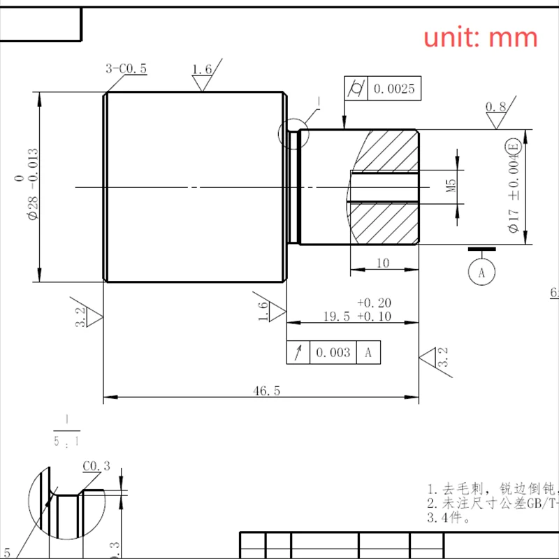
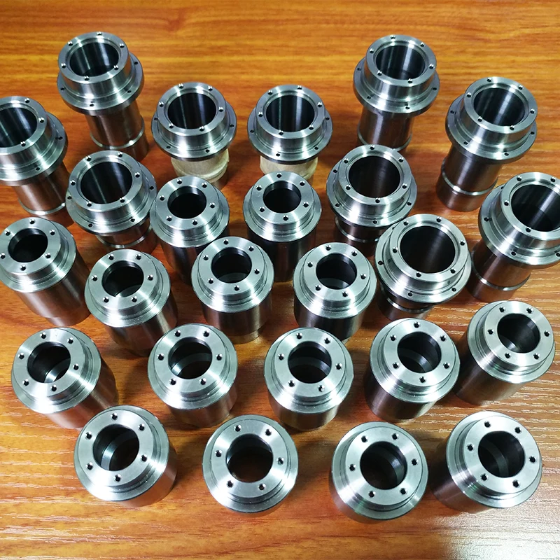
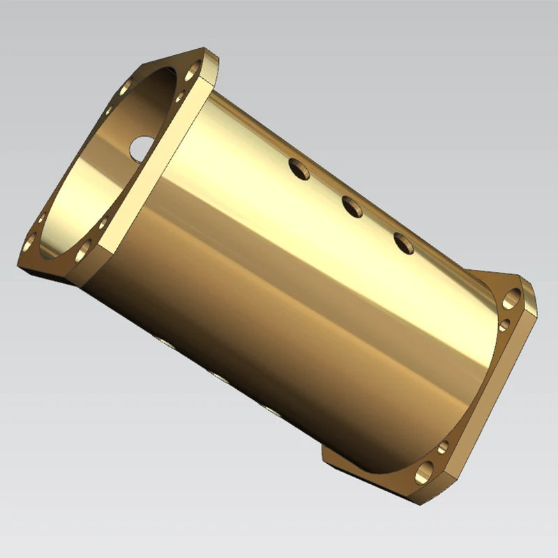
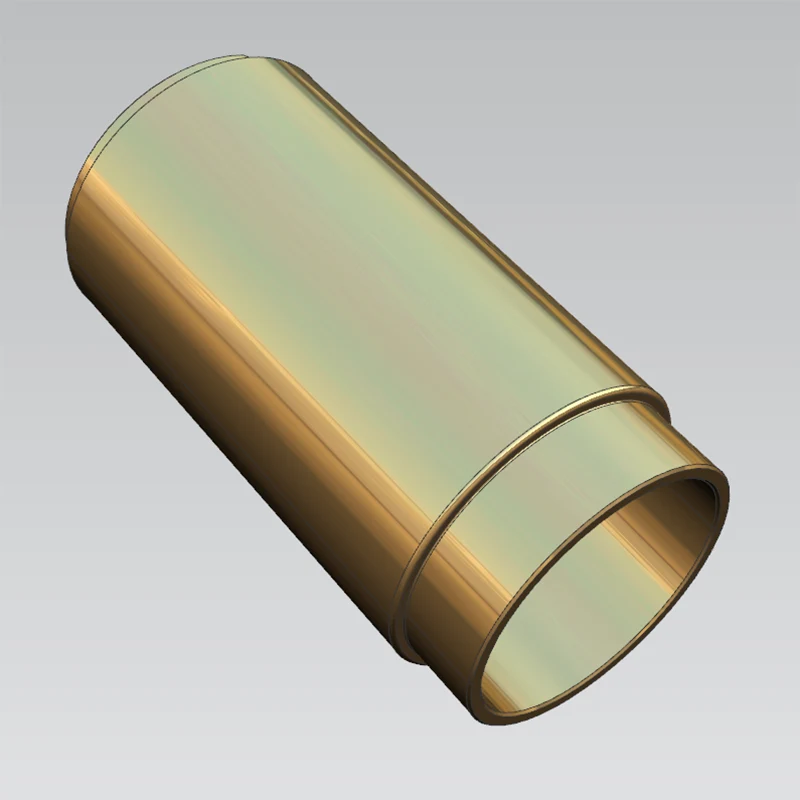
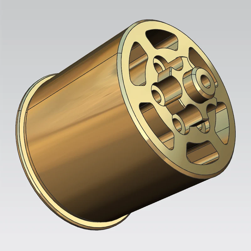
Workpiece: Rotor mount for 50-series industrial motors
Material: TC4 titanium alloy
Application: A core load-bearing and mating component within industrial motors. The product must meet dual requirements for structural lightweighting and high strength under alternating loads, necessitating extremely strict control over geometric and dimensional tolerances.
Drawing Specifications: Coaxiality between the critical mating inner bore and outer diameter must be ≤0.02mm; all unspecified geometric tolerances must comply with the GB/T 1184-h standard; strict control is also required for end-face runout and the positional accuracy of the outer profile relative to internal locating slots.
Inherent Material Challenges: TC4 titanium alloy has very low thermal conductivity and high ductility/toughness, resulting in slow heat dissipation during cutting. This makes the material prone to tool adhesion, workpiece deflection (tool push-off), and localized thermal deformation. Conventional CNC turning—hampered by errors from multiple setups and insufficient tool rigidity—cannot consistently meet micron-level geometric tolerance requirements.
Previous Outsourcing Issues: The initial supplier used a conventional turning process involving multiple setups; coaxiality consistently exceeded tolerances. Post-assembly, the motors exhibited excessive vibration and noise levels (surpassing design thresholds) during both no-load and loaded operation, and repeated rework failed to bring the parts up to standard.
3.1. Clamping Process Optimization: Abandoned the multi-setup approach in favor of a single-setup method using a unified datum. The outer diameter, end face, and mating inner bore are finish-machined in one operation, completely eliminating datum shift errors caused by multiple setups.
3.2. Rough Machining Allowance Control: A uniform finishing allowance of 0.2mm is reserved for all critical mating surfaces. This prevents unbalanced cutting forces during the finishing stage—caused by uneven stock—and further minimizes the risk of tool push-off. 3.3. Cutting Cooling and Parameter Matching: Continuous spray cooling using an extreme-pressure cutting fluid specifically formulated for TC4 titanium alloy is employed throughout the process to rapidly dissipate heat and suppress thermal deformation. During the finishing stage, specialized cutting parameters—featuring low speeds and high feed rates—are matched with high-rigidity, vibration-dampening tooling to mitigate the elastic deflection characteristic of titanium alloys.
3.4. Finishing of Complex Structures: As internal locating slots and mounting holes cannot be formed via a single turning operation, customized locating fixtures are used for subsequent processing; this minimizes fixture-induced repeatability errors and ensures that the positional accuracy of the slots and internal holes relative to the datum meets specifications.
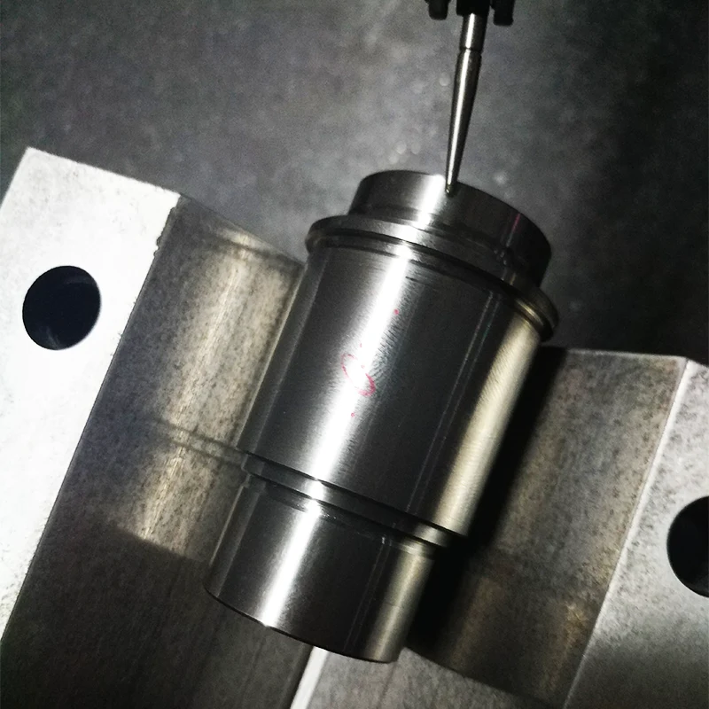
Comprehensive Inspection Equipment: Coordinate Measuring Machine (CMM) and high-precision roundness tester; 100% inspection of critical dimensions.
Measured Precision Data: Coaxiality between internal and external diameters is consistently ≤0.01 mm; end-face runout is ≤0.008 mm. All form and position tolerances, as well as dimensional tolerances, comply with both the engineering drawings and the GB/T 1184-h national standard.
Project Feedback: Prototype samples passed the customer's third-party acceptance test on the first attempt. The rotor mount demonstrated excellent assembly fit, and the fully assembled motor's vibration and operating noise levels returned to design standards. Mass-produced units are currently operating stably in the field; structural strength and lightweighting metrics meet all usage requirements, leading the customer to designate this as a long-term outsourced contract for all subsequent orders of the same model.
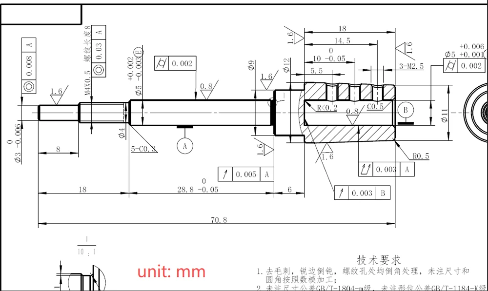
Workpiece: 70B series high-speed industrial motor drive shaft.
Raw Material: Quenched and tempered 40Cr steel; finished base hardness of HRC 32–36.
Application Scenario: Core shaft component for high-speed rotational power output; subjected to prolonged, high-frequency, high-speed operation, requiring exceptional fatigue strength, rotational precision, and dynamic balance performance.
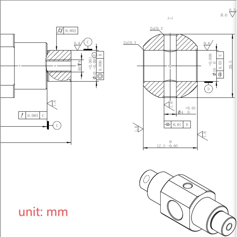
Mandatory Precision Specifications: Coaxiality of multiple critical mating journals ≤0.01 mm; journal end-face runout ≤0.01 mm. Additionally, positional accuracy must be controlled for end-face threaded holes and circumferential keyways relative to the journal datum. Challenges in initial material processing: After quenching and tempering, the 40Cr substrate hardness increases, resulting in high cutting resistance and rapid wear on conventional carbide tools; during high-speed cutting, the shaft is prone to deformation caused by the release of cutting stresses and radial tool deflection, leading to a loss of rotational accuracy.
Pain points with the client's previous outsourced processing: The former supplier used segmented turning and multiple clamping setups, resulting in consistently excessive journal coaxiality errors and failure to meet dynamic balance standards; the motor vibrated violently during high-speed operation, and repeated rework failed to resolve issues related to stress-induced deformation and clamping errors.
3.1. Integrated clamping and machining: A single clamping setup using a unified datum allows for the simultaneous machining of multi-step cylindrical surfaces and mating end faces, eliminating issues caused by inconsistent datums in segmented processing.
3.2. Optimization of machining allowance and chip evacuation: A uniform 0.3mm finishing allowance is reserved during the rough machining of critical journals; a high-pressure internal cooling system is employed to flush the cutting zone in real-time, simultaneously cooling the part and evacuating chips, thereby preventing secondary surface scratching and minimizing thermal deformation.
3.3. Finishing strategy: Ultra-fine-grained, high-rigidity carbide tools are selected, and a progressive layer-reduction cutting process is used to gradually release internal cutting stresses and control radial tool deflection, ensuring long-term dimensional stability for long shaft components.
3.4. Finishing of auxiliary features: Threaded holes on end faces and circumferential keyways are machined using specialized coaxial positioning fixtures aligned with the journal's rotational datum, ensuring the positional accuracy of these features meets drawing tolerances.
Comprehensive inspection equipment: Coordinate Measuring Machine (CMM), high-precision roundness tester, and dynamic balancing tester; dual full-scale inspection covering both dimensions and dynamic balance. Measured precision data: Multi-stage journal coaxiality is consistently ≤0.008 mm, and axial runout is ≤0.005 mm; all geometric and positional tolerances meet specifications, and the rotor shaft passes the initial dynamic balance test without requiring re-balancing.
Project implementation feedback: Prototypes passed acceptance inspection on the first attempt, and vibration and noise levels during high-speed operation comply with national standards for industrial motors; batch-produced shafts show no stress-induced deformation or abnormal wear during operation, with strength and rotational stability meeting long-term service requirements, leading to a long-term outsourcing partnership with the client.
Address
Guangming District, Shenzhen City, Guangdong Province, China
Tel


